RATED CAPACITY LIMITER OPERATOR MANUAL NBT60XL
7-20 Published 11-01-2020 Control # 710-00
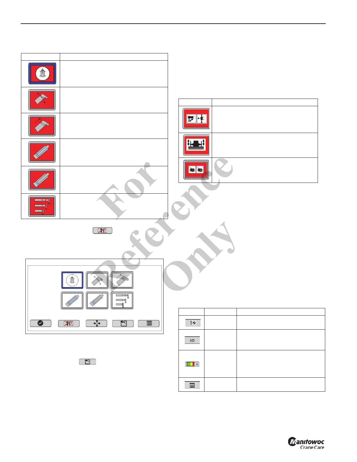
The calibration reset button resets all calibrations
while in the Calibration screen.
Main Sensor Calibration Menu
Use the right arrow key to move to the function keys.
Select ESC button to return to the System
Configuration menu screen without deleting any limit values.
A password is required to calibrate a sensor. For more
information, see “Entering the System Configuration
Password” on page 7-18.
COMPONENT ADDRESSING
Table 7-13 shows the component addressing warning icons.
These icons may appear after a component is replaced.
For more information about component addressing, see the
Service Manual.
DIAGNOSTICS
The Diagnostics Menu screen contains crane and truck
operating information and warnings, an hour meter, and fault
code displays.
About the Diagnostics Screen
Machine information/warnings display in upper left hand
corner of the Diagnostics Menu screen.
Table 7-14 shows the navigation buttons on the bottom of the
Diagnostics screen. Use the function key to use the
appropriate function key to navigate to the next screen.
Table 7-12 Sensor Calibration Warnings
Icon Description
Slew Angle — Indicates that the slew
sensor needs to be calibrated.
Boom Angle — Indicates that the boom
angle sensor needs to be calibrated.
Boom Length — Indicates that the boom
length sensor needs to be calibrated.
Lift Cylinder Rod Pressure Transducer
— Indicates that the rod side transducer
located on the lift cylinder needs to be
calibrated.
Lift Cylinder Base Pressure Transducer
— Indicates that the base side transducer
located on the lift cylinder needs to be
calibrated.
Outrigger Sensor — Indicates that the
sensors on the outriggers needs to be
calibrated.
Table 7-13 Component Addressing Warnings
Icon Description
Outrigger Control Panel(s)—Indicates
that the outrigger control panel(s) need a
CAN bus address.
Counterweight Control Panel(s)—
Indicates that the counterweight control
panel(s) need a CAN bus address.
Hoist Module(s)—Indicates that the hoist
module(s) need a CAN bus address.
Table 7-14 Diagnostics Navigation Keys
Icon Key Description
Button #1
Navigates to Diagnostic Screen 2
(Fault Codes) when pressed.
Button #2
Navigates to real-time Input/
Output (I/O) screen when
pressed.
Button #4
Appears only when a valid crane
configuration has been entered
and navigates to RCL Operating
Mode Screen.
Button #5
Navigates to Main Screen when
pressed.
Fo
r
Reference
Only
 Loading...