SET-UP OPERATOR MANUAL NBT60XL
4-28 Published 11-01-2020 Control # 710-00
9. Using counterweight control panel (Figure 4-16) located
on either side of superstructure, lower the counterweight
removal cylinders. For more information, see Lowering
the Counterweight Cylinders, page 4-24.
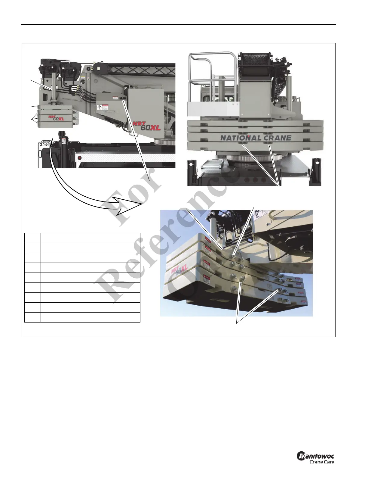
10. Attach removable counterweight to cylinders using
section attachment pins (6, Figure 4-20).
11. Using the counterweight control panel (Figure 4-16),
fully raise counterweight removal cylinders. For more
information, see Raising the Counterweight Cylinders,
page 4-24.
12. Adjust bolts (8, Figure 4-19) as needed to level the
counterweight and eliminate any relative motion
between the upper and lower counterweight. Tighten the
jam nuts (9) to lock the counterweights into position.
13. Repeat steps 4 to 12 as necessary for the remaining
counterweight sections.
Stowing the Bottom Counterweight(s)
1. Position crane on a firm, level surface.
2. Fully extend and set the outriggers, then level the crane
(see Setting the Outriggers, page 4-2).
FIGURE 4-20
1 Counterweight Section — Top
2 Counterweight Sections — Bottom
3 Removal Cylinders
4 Superstructure Attachment Pin
5 Cylinder Attachment Pin
6 Section Attachment Pin
7 Counterweight Control Panel
8Bolt
9 Jam Nut
1
2
3
4
7
10261
5
8
9
10264
(3 Places per CWT)
10263
16000 lb (7558 kg)
Configuration Shown
6
Fo
r
Reference
Only
 Loading...