NBT60XL OPERATOR MANUAL CONTROLS AND OPERATING PROCEDURES
NATIONAL CRANE Published 11-01-2020 Control # 710-00 3-19
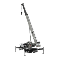
Heater Coolant
The heater coolant bottle (1, Figure 3-11) is mounted to the
air conditioner. The coolant should contain a minimum 50/50
ratio mixture of water and antifreeze to prevent freezing or
slushing.
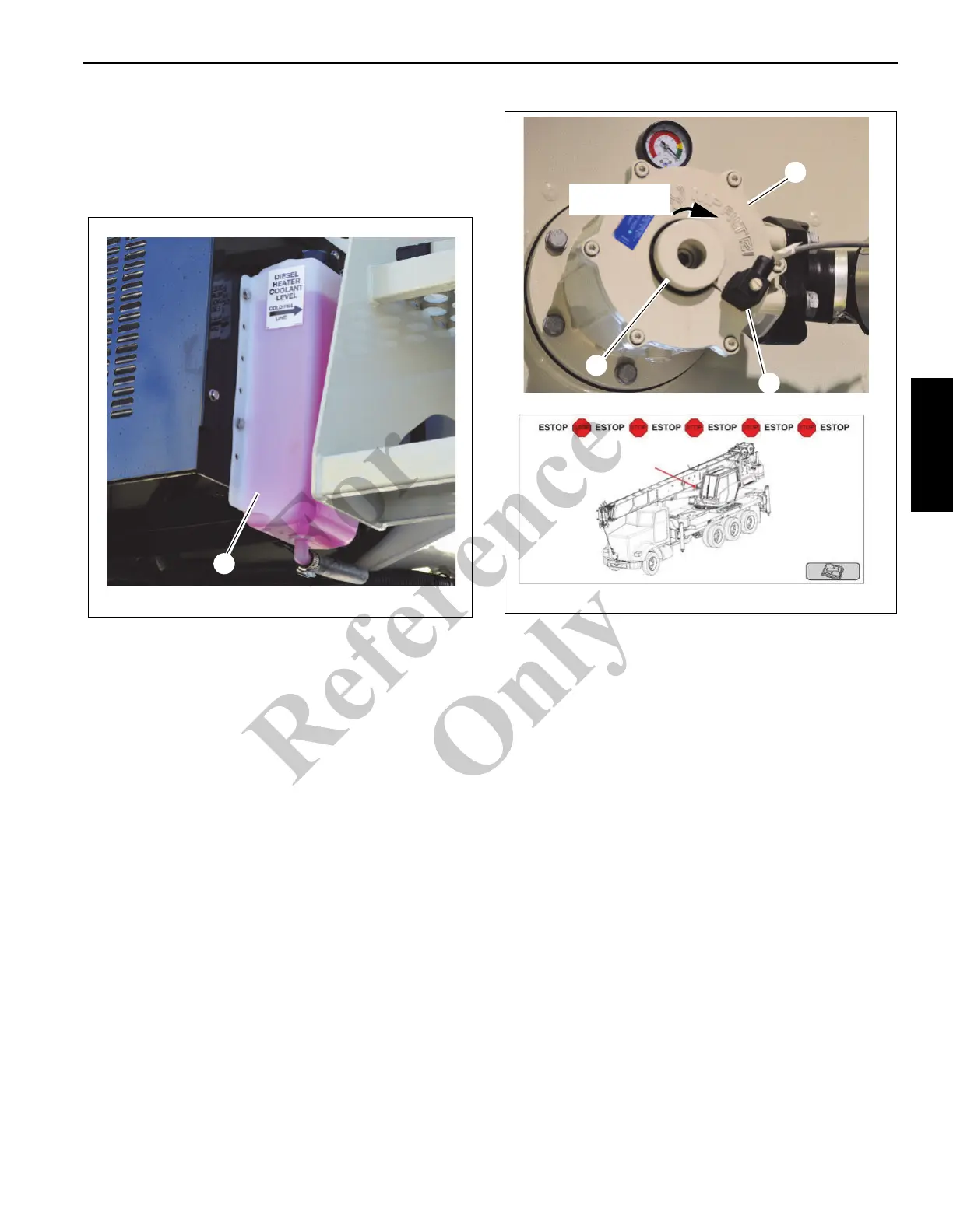
Hydraulic Suction Pump Shut-off Valve
The hydraulic suction pump (1, Figure 3-12) is located on the
front of the hydraulic tank. The pump features a safety switch
(2) that determines if the shut-off valve is open or shut. The
valve must be fully open to start and operate the crane.
When the valve is closed, the crane will not start. This safety
switch ensures that there is hydraulic fluid available when
running the crane. For more information about the control
states, see “Crane Ignition and Control States” on page 3-3.
When the suction valve is closed, the ESTOP warning
screen appears in the RCL (Figure 3-12). The ESTOP
screen persists until the suction valve is fully open.
To open the valve, turn the handwheel (3) clockwise.
OPERATING PROCEDURES
You need to be familiar with the safety precautions outlined
in the section titled Safety Precautions, page 2-1 before
operating the crane.
Equipment Familiarization
All members of the crew should become familiar with the
location and operation of the controls, the correct operating
procedures, the maximum lifting capacities, and the Safety
Precautions in Section 2 of this manual. Carefully follow the
operating procedures outlined below and the information in
the load charts located in the crane cab.
Crane Cab Access
To enter the crane cab use the ladder (1, Figure 3-13)
stowed next to the cab on the carrier decking and position it
as shown in Figure 3-13. The ladder is secured in position
with catches (4). After opening the cab door, climb the ladder
and at the same time grasp the grab handles (2) in the cab
doorway to enter the cab. Do not try to access the crane cab
by other means. When done, release the ladder using
release handle (5) and lift and rotate to the stowed position.
Turn clockwise to
open valve
9607
FIGURE 3-12
9608
2
3
1
Fo
r
Reference
Only
 Loading...