SET-UP OPERATOR MANUAL NBT60XL
4-26 Published 11-01-2020 Control # 710-00
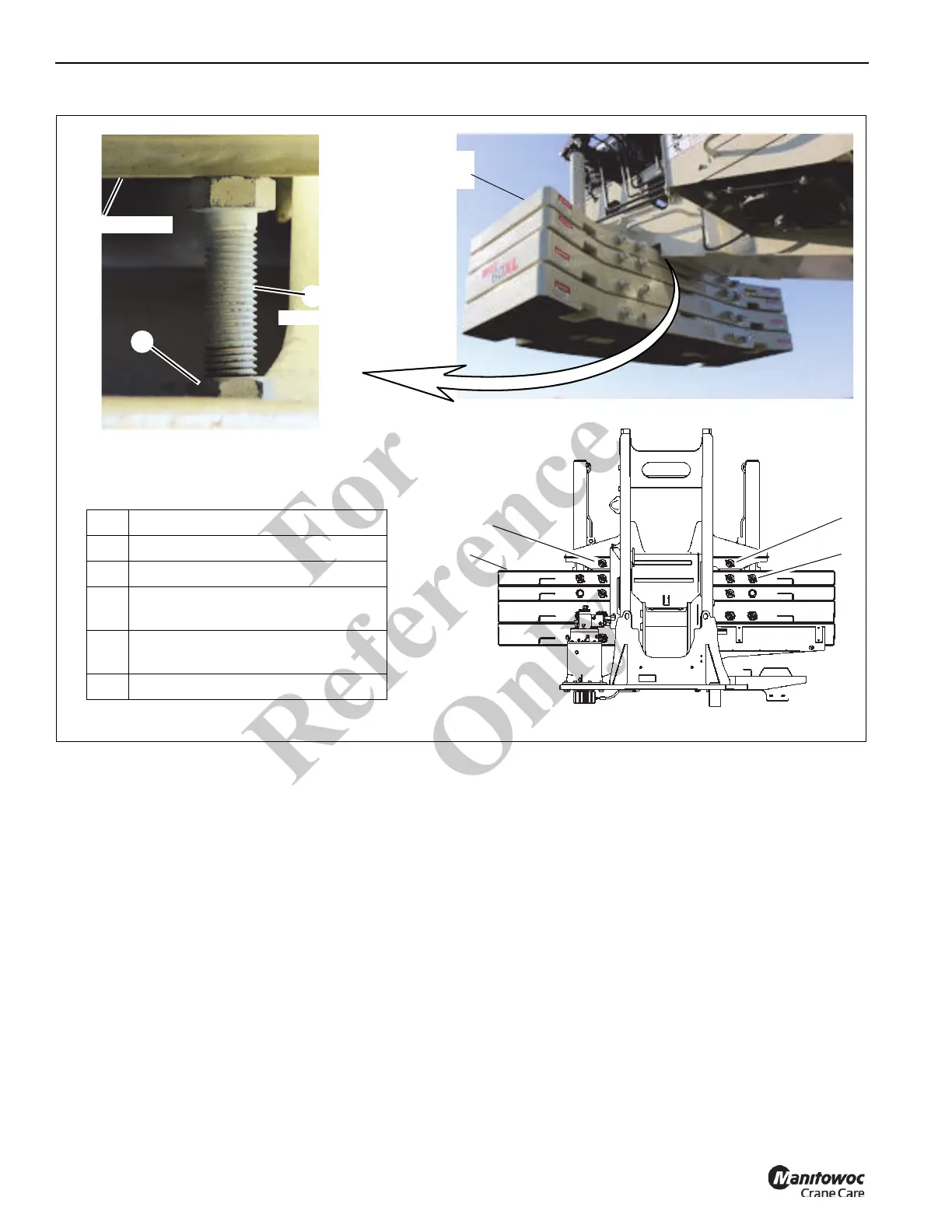
Stowing the Top Counterweight on the
Carrier Deck
Use the following procedure to stow the 3000 lb (1360.8 kg)
or 5000 lb (2268 kg) top counterweight section (3,
Figure 4-18) on the NBT60XL.
1. Position crane on a firm, level surface.
2. Fully extend and set the outriggers, then level the crane
(see Setting the Outriggers, page 4-2).
3. (Optional) Set the camera display to view the rear view
camera as necessary.
4. Set display in Operator’s Console to the
RCL Operating
Mode Screen (Figure 4-17) (see Section 7, Rated
Capacity Limiter
).
5. While watching the RCL display, rotate superstructure
so boom is over the rear of the crane and
counterweights are over the counterweight stowage
area. Pull the House Lock handle on the console to
engage the house lock. Using the house lock will assist
in aligning the counterweights. For more information,
see House Lock, page 3-12.
The Counterweight Removal Slew Position Indicator
(yellow arrows) (1, Figure 4-17) appears in the RCL
display, which indicates the rear of the superstructure is
nearly directly above the counterweight stowage area on
the carrier deck.
Ensure vertical alignment of counterweight to the
counterweight mounting lugs on the carrier deck or top
counterweight section to bottom counterweight section
with the optional rear view camera or by leaving the cab
and performing a visual inspection. If necessary, retract
the house lock and rotate the superstructure until
alignment is achieved.
Superstructure
2
1
FIGURE 4-18
Top
Counterweight
(3 places)
9664
10263
10262
4
5
3
1Bolt
2 Jam Nut
3 Counterweight Section — Top
4
Superstructure Attachment Pin,
Right Side
5
Superstructure Attachment Pin, Left
Side
6 Cylinder Attachment Pin
16000 lb (7558 kg)
Configuration Shown
6
Fo
r
Reference
Only
 Loading...