SET-UP OPERATOR MANUAL NBT60XL
4-2 Published 11-01-2020 Control # 710-00
onto the rest). If necessary, relevel the crane using the
procedures under Setting the Outriggers, page 4-2.
Bubble Level Adjustment
The bubble level adjustment should be checked periodically;
if it is suspected that the bubble level indicator is out of
adjustment, verify and adjust the bubble level as follows:
1. Position the crane on a firm, level surface.
2. Extend and set the outriggers. Level the crane, as
indicated by the bubble level indicator, using the
outriggers.
3. Place a miracle pointer level, carpenter level, or similar
type device on a machined surface such as the turntable
bearing or bearing mounting surfaces.
4. Using the outriggers, level the crane as indicated on the
leveling device used in step 3.
5. Using the bubble level indicator mounting screws, adjust
the bubble level indicator to show level.
Site Selection
The outrigger floats must be on a firm solid surface that is
level. The surface must keep the crane stable and not allow
the stabilizer float to sink or slide. Avoid areas that are:
• uneven
• rocky
• muddy
Setting the Outriggers
The outrigger setup procedure is as follows:
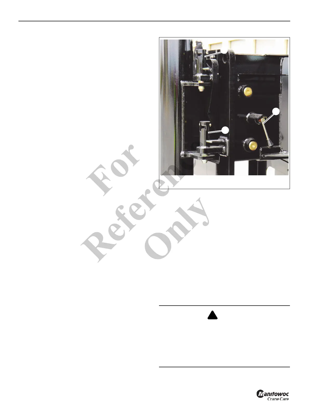
1. Disengage the mechanical travel lock (1, Figure 4-1)
that secures each outrigger beam in the fully retracted
position during travel.
NOTE: To ensure a true reading always make sure the cab
tilt is completely lowered.
2. Operate the ground station or cab outrigger control
panel
(see Figure 3-1).
3. Select the desired outrigger beam with the extension
button and press the extend button to extend the
outrigger beams.
4. Set all four outrigger beams to desired position:
a. 0% extended position. Does not require the
outrigger beams to be extended.
b. 50% extended position. Engage the manual over-
center locks (2, Figure 4-1) for the midpoint position.
c. (NTC60XL only) 75% extended position. Engage
the manual locks (3, Figure 4-1) by rotating the
handle clockwise.
d. Fully extended position. All locks should be
disengaged for the fully extended position.
DANGER
All four outriggers must either be fully retracted (0%), at
the midpoint (50%), three-quarters (75%) (NTC60XL
only), or fully extended (100%), and the RCL set to the
correct position. Failure to do so creates a tipping hazard.
Do NOT use position locks in combination. Using more
than one position lock at a time may result in an undesired
span.
Fo
r
Reference
Only
 Loading...


