SET-UP OPERATOR MANUAL NBT60XL
4-10 Published 11-01-2020 Control # 710-00
JIB MAINTENANCE
1. Lubricate as outlined in the section titled Lubrication
Procedure and Charts, page 5-1.
2. Check for free rotation of jib sheave daily when using jib.
Setting the Offset on the Telescopic Jib
Use the following procedure to set the offset for the following
jibs:
• 26 to 45 ft (7.9 to 13.7 meters) Telescoping Offset Jib—
This jib can be offset at 0 and 30 degrees.
For information about how to set the jib offset for the lattice
jib, see Setting the Offset on the Lattice Jib, page 4-10.
1. Extend and set the outriggers. Swing the boom over rear
of truck chassis.
2. To set the offset from zero degrees (0°) to thirty degrees
(30°), perform the following:
a. Slowly lower the boom until the tip of the jib is on the
ground and the pressure on the offset pin (1,
Figure 4-5) is relieved.
b. Remove the lock pin (2) and offset pin (1).
c. Deploy the offset mast in the extended up position.
See Setting the Offset Mast, page 4-13.
d. Slowly elevate and telescope the boom at the same
time until the offset shaft takes the full load of the jib.
3. To set the offset from thirty degrees (30°) to zero
degrees (0°), perform the following:
a. Slowly lower the boom until the tip of the jib is on the
ground and the offset pin (1) can be installed.
b. Install the offset pin (1) and lock pin (2).
c. Deploy the offset mast in the extended up position.
See Setting the Offset Mast, page 4-13.
d. Raise the boom and operate as desired.
Setting the Offset on the Lattice Jib
The lattice boom can be set to the following positions:
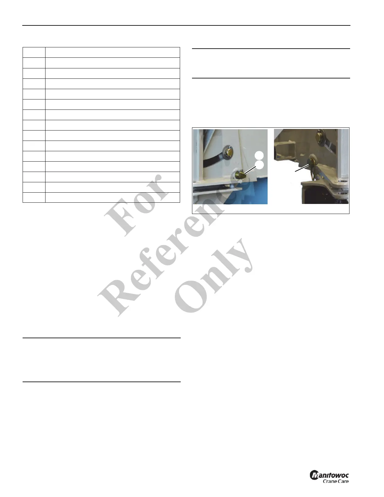
• 30-degree offset—The offset pins are removed and
stowed in the storage bushings (Figure 4-6).
• 15-degree offset—The offset pins are installed in the 15-
degree offset slot (Figure 4-7).
• 0-degree offset—The offset pins are installed in the
uppermost offset positions (Figure 4-8).
Use the following procedures to set the offset on the 36.5 ft
lattice jib.
Item Description
1 Boom Base Section
2 Tele 1
3 Tele 2
4 Tele 3
5 Jib Swing Pin
6 Right Side Attachment Pins
7 Left Side Attachment Pins
8 Jack Handle
9 Mast Assembly Stowage Pin
10 Mast Assembly
11 Mast Assembly Cable Retainer
12 Offset Pin
13 Upper Sheave Cable Retainer
14 Alignment Jack
CAUTION
The mast assembly (10, Figure 4-4) must be positioned
on top of the base section before attempting to use the jib
at 0 degree or 30 degree offset positions. Failure to do so
can cause damage to the mast and/or jib adapter.
CAUTION
Do not overload the jib or the attachment points when
lowering the boom.
Fo
r
Reference
Only
 Loading...


