PREVENTATIVE MAINTENANCE CD5515-2/YB5515-2 SERVICE MANUAL
5-30 Published 1-20-2017, Control# 483-02
6. When the tank is empty, disconnect the two hydraulic
lines from the rear of the hydraulic oil tank (Figure 5-51).
Remove the suction strainer from the suction port and
clean it in a suitable solvent.
7. Clean the inside of the hydraulic tank and remove any
sediment.
8. Install the fill strainer, suction strainer, suction hose and
return line to the hydraulic tank.
9. Replace the hydraulic oil filter. See “Replace the
Hydraulic Oil Filter.”
10. Fill the hydraulic tank with Mobil Fluid 424 hydraulic oil to
the level of the sight glass.
11. After the tank is filled, start the engine and operate each
function until all the cylinders and lines are filled.
12. Fully retract and lower the boom and retract the
outriggers. Check the hydraulic oil level. Oil must be to
the level of the sight glass. Add hydraulic oil if
necessary.
13. Visually check for leaks.
Replace the Hydraulic Oil Filter
1. Engage the parking brake and shut off the engine.
NOTE: It is necessary to climb under the crane to replace
the hydraulic oil filter. Be sure engine is shut off, the
ignition key is removed and chock blocks are in
place before climbing under the crane.
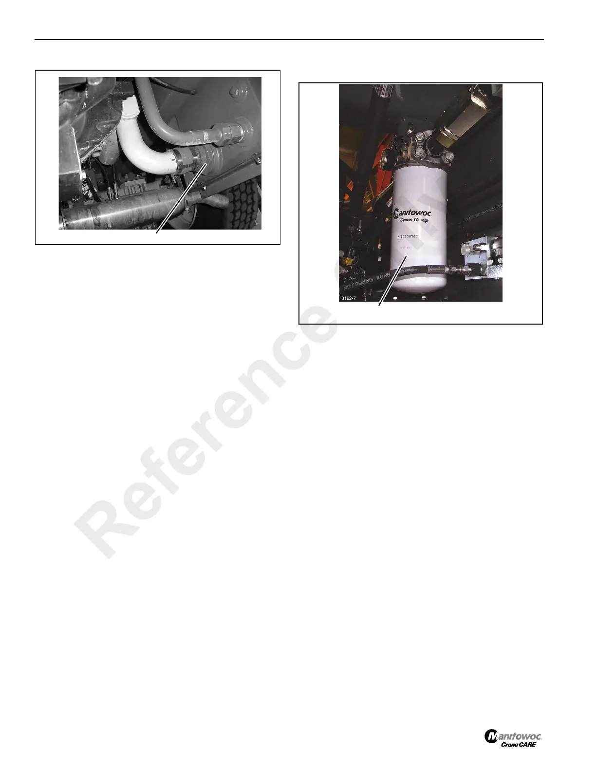
2. Locate the hydraulic oil filter under the machine
(Figure 5-52).
3. Remove the filter:
a. Using a filter wrench, turn the filter counterclockwise
to loosen and remove the filter. Properly discard the
removed filter.
b. Clean the mounting surface on the filter head for the
filter.
4. Install the filter:
a. Apply a small amount of clean hydraulic oil to the
gasket of the new hydraulic filter. Install the filter.
Install the filter to the filter head by turning it
clockwise until the filter gasket makes contact.
Then, tighten the filter 1/2 to 3/4 turn to achieve a
tight seal.
b. Start the engine and check for leaks around the
filter.
Tank Hoses and Suction Strainer
FIGURE 5-51
p0426
Hydraulic Filter
FIGURE 5-52
Reference Only
 Loading...


