CD5515-2/YB5515-2 SERVICE MANUAL
9-10 Published 1-20-2017, Control# 483-02
Disassembly
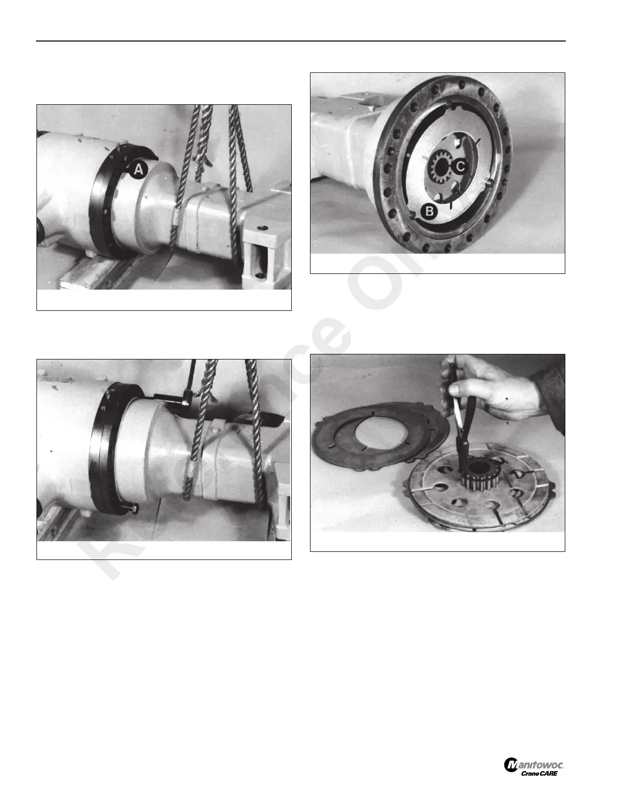
1. Support the axle arm Figure 9-12 and remove bolts A.
2. Jack the axle arm off the drive head, using drive head
securing bolts Figure 9-13. Remove all traces of gasket
from the mating surfaces.
3. There are two counterplates B Figure 9-14 one at each
end of the brake pack, which are secured to the plate
carrier C. If the plates are to be reused, note their
position and which way round they are then remove the
brake pack.
4. Remove the retaining ring Figure 9-15. If the brake pack
is to be reused, note the position of the plates before
removing them.
NOTE: The planet carrier has an internal chamber at the
end which faces away from the drive head.
5. Wear limit of friction plates is to the depth of the
circumferential grooves X Figure 9-16. Check all plates
for flatness and damage. (Some scoring of the
counterplates is normal.) Completely replace the brake
pack if worn or damaged. Do not replace individual
plates.
Reference Only
 Loading...


