EasyManuals Logo
Home>Manitowoc>Construction Equipment>Shuttlelift CD5515-2

Manitowoc Shuttlelift CD5515-2 Service And Maintenance Manual

Manitowoc Shuttlelift CD5515-2
293 pages
To Next Page IconTo Next Page
To Previous Page IconTo Previous Page
Page #216 background imageLoading...
Page #216 background image
GROVE Published 1-20-2017, Control# 483-02 9-11
CD5515-2/YB5515-2 SERVICE MANUAL
9
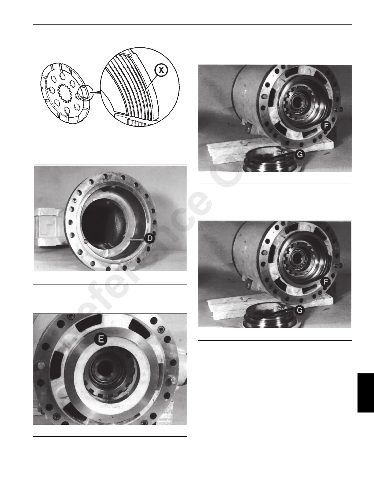
6. Remove the three reaction pins D Figure 9-17. Inspect
for damage.
7. Carefully remove brake piston E Figure 9-18 from its
housing, if removal is necessary. A hydraulic hand pump
can be used to force the piston out of the housing.
8. Remove and discard seals F and G Figure 9-19. Inspect
the housing for damage and scoring. Nicks or cuts in the
seals may be responsible for loss of brake fluid.
Assembly
1. Install new seals F and G Figure 9-20. Make sure they
seat squarely in their grooves.
2. Carefully press piston E Figure 9-21 all the way into its
housing.
FIGURE 9-16
a0228
FIGURE 9-17
p0092
FIGURE 9-18
p0093
FIGURE 9-19
p0094
FIGURE 9-20
p0094
Reference Only

Table of Contents

Other manuals for Manitowoc Shuttlelift CD5515-2

Questions and Answers:

Question and Answer IconNeed help?

Do you have a question about the Manitowoc Shuttlelift CD5515-2 and is the answer not in the manual?

Manitowoc Shuttlelift CD5515-2 Specifications

General IconGeneral
BrandManitowoc
ModelShuttlelift CD5515-2
CategoryConstruction Equipment
LanguageEnglish

Related product manuals