CD5515-2/YB5515-2 SERVICE MANUAL
9-12 Published 1-20-2017, Control# 483-02
3. Assemble the friction plates and counterplates onto the
carrier. If the original brake pack is being reused, return
the plates to their original positions (see Disassembly
step 3). Soak new friction plates in gear oil before
assembly. Install retaining ring Figure 9-22.
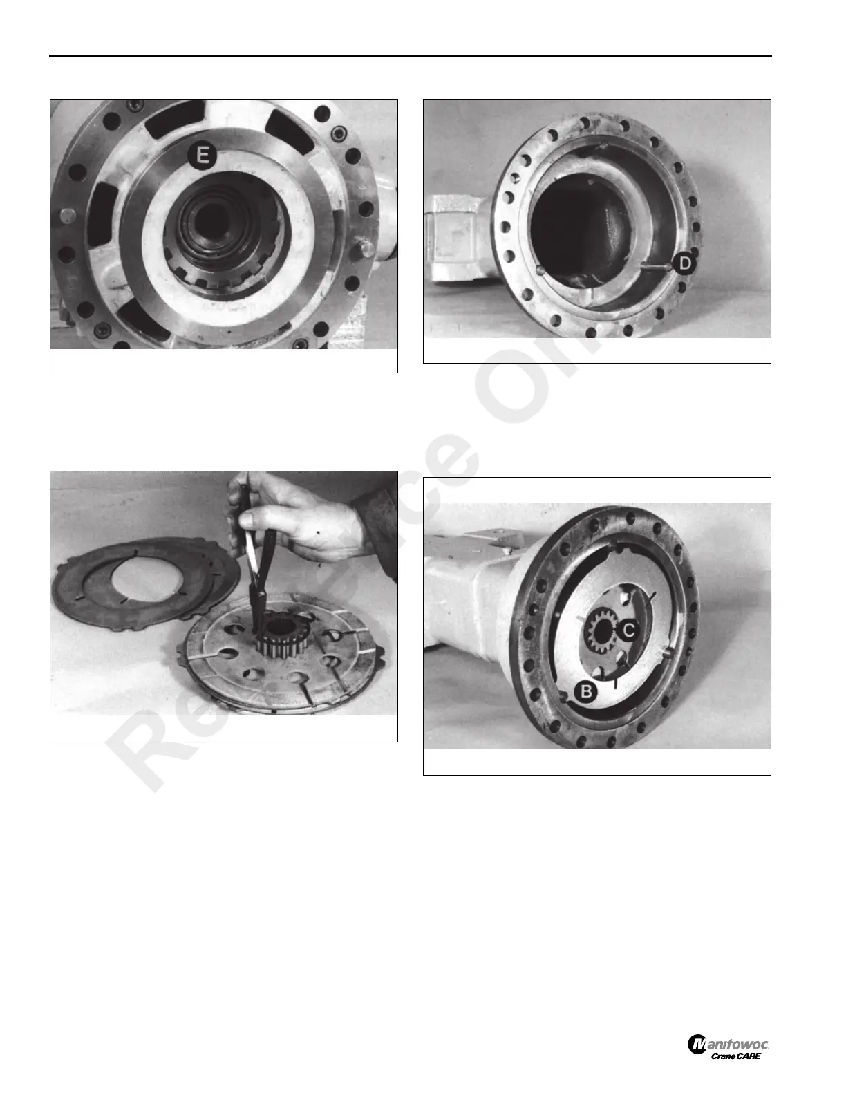
4. Locate the three reaction pins D Figure 9-23 into their
grooves, securing them with grease. Push the pins fully
into their location holes in the housing.
5. Install one counterplate B Figure 9-24 into the housing,
then the brake pack, then the other counterplate. Ensure
that the chamfered end of the brake carrier C faces
away from the drive head. Return reused counterplates
to their original positions. Push the brake pack fully
home.
6. Apply Loctite® 275 to the mating face of the drive head.
Locate the axle arm onto the drivehead, with the
embossed word “TOP” on the axle arm up most.
Reference Only
 Loading...


