GROVE Published 1-20-2017, Control# 483-02 10-17
CD5515-2/YB5515-2 SERVICE MANUAL STEERING SYSTEM
12. A small mark has been made with a pumice stone on
both spool and sleeve close to one of the slots for the
neutral position springs (Figure 10-25). If the mark is not
visible, remember to leave a mark of your own on sleeve
and spool before the neutral position springs are
dismantled.
13. Carefully remove the spool out of the sleeve (2,
Figure 10-18).
14. Press the neutral position springs (9) out of their slots in
the spool.
15. Remove dust seal and O-ring / Kin-ring / Roto Glyd
(Figure 10-27).
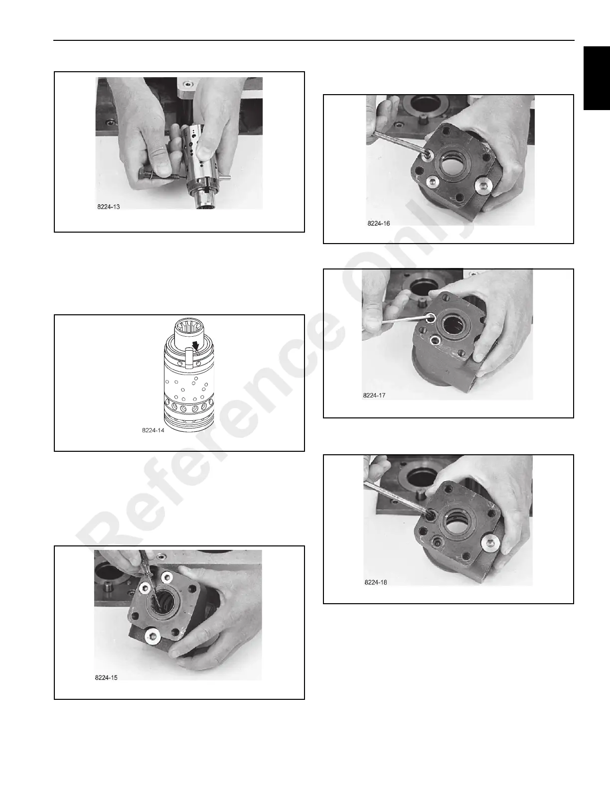
16. Remove plugs from shock valves using a 6 mm Allen
wrench (Figure 10-27).
17. Remove seal washers (Figure 10-28).
18. Unscrew the setting screws using a 6 mm Allen wrench
(Figure 10-29).
19. Shake out the two springs and two valve balls into your
hand (Figure 10-30). The valve seats are bonded into
the housing and cannot be removed.
Reference Only
 Loading...


