GROVE Published 1-20-2017, Control# 483-02 10-23
CD5515-2/YB5515-2 SERVICE MANUAL STEERING SYSTEM
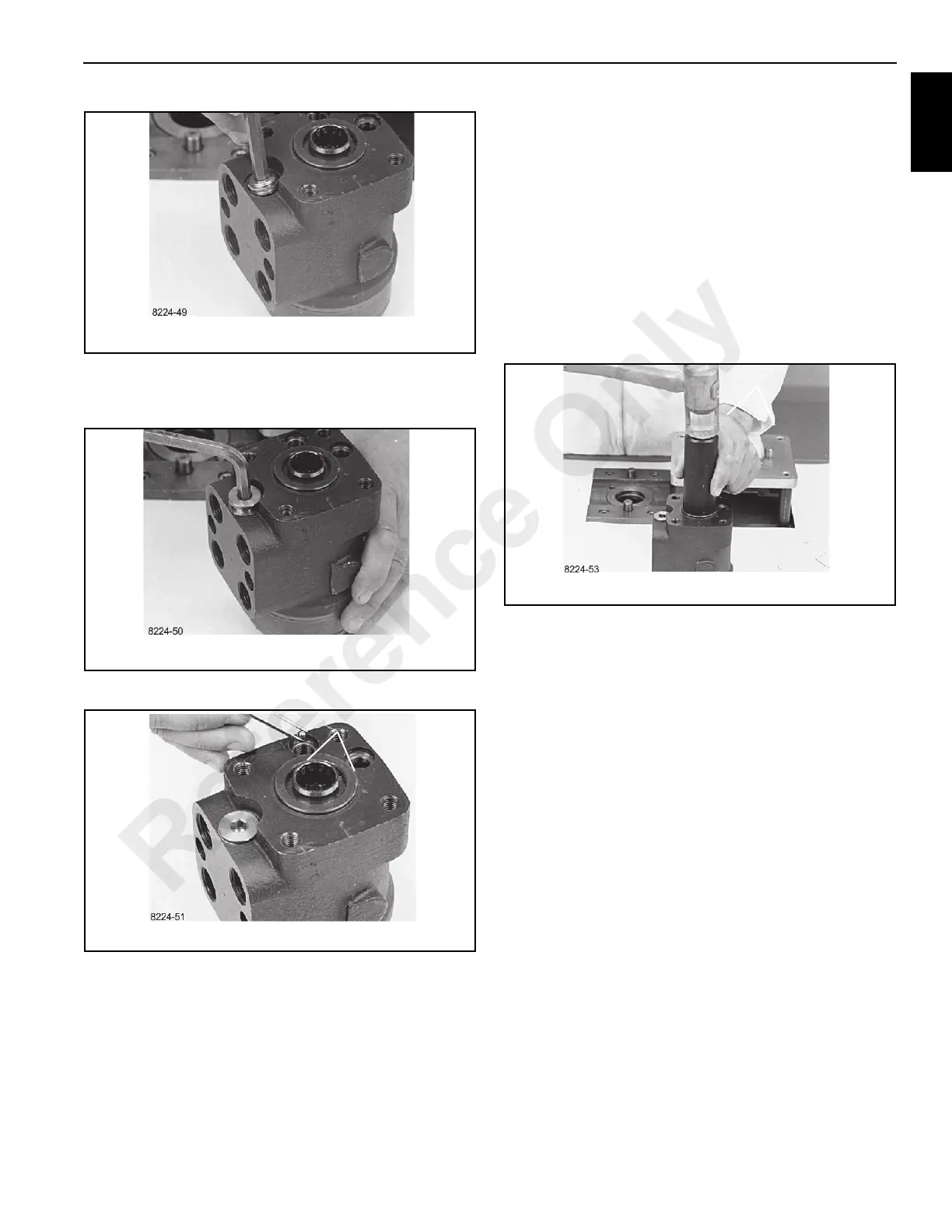
32. Screw plug with dust seal into the housing using an 8
mm Allen wrench. Tightening torque: 65 ±5 Nm (575.3 ±
44.2 lb in).
33. Put a ball in the two holes indicated.
34. Place springs and valve cones over the two balls.
NOTE: The blue spring applies to setting range 90-180 bar
(1305-2610 psi). The untreated spring applies to
setting range 170-260 bar (2465-3770 psi).
35. Screw in the two setting screws using a 6 mm Allen
wrench. Make the pressure setting on a panel or the
vehicle.
36. Screw plugs with seal rings into the two shock valves
and tighten them with a torque of 30 +10 Nm (265.5 +
88.5 lb in) using a 6 mm Allen wrench.
37. Fit the dust seal ring in the housing using special tool
and a plastic hammer.
Installation
1. Locate the steering orbitrol and steering column in
position on the mounting bracket under the instrument
panel. Secure in place with four bolts and numerous flat
washers.
2. Connect the hydraulic lines to the steering orbitrol.
3. Check the hydraulic oil level in the reservoir. Fill if
necessary.
4. Start the engine and turn the steering wheel in both
directions to fill the lines with hydraulic fluid and bleed air
from the system. Check for leaks and repair if necessary.
5. Check the hydraulic oil level in the reservoir. Fill if
necessary.
6. Install the outside cover to the operator’s compartment.
Reference Only
 Loading...


