STEERING SYSTEM CD5515-2/YB5515-2 SERVICE MANUAL
10-22 Published 1-20-2017, Control# 483-02
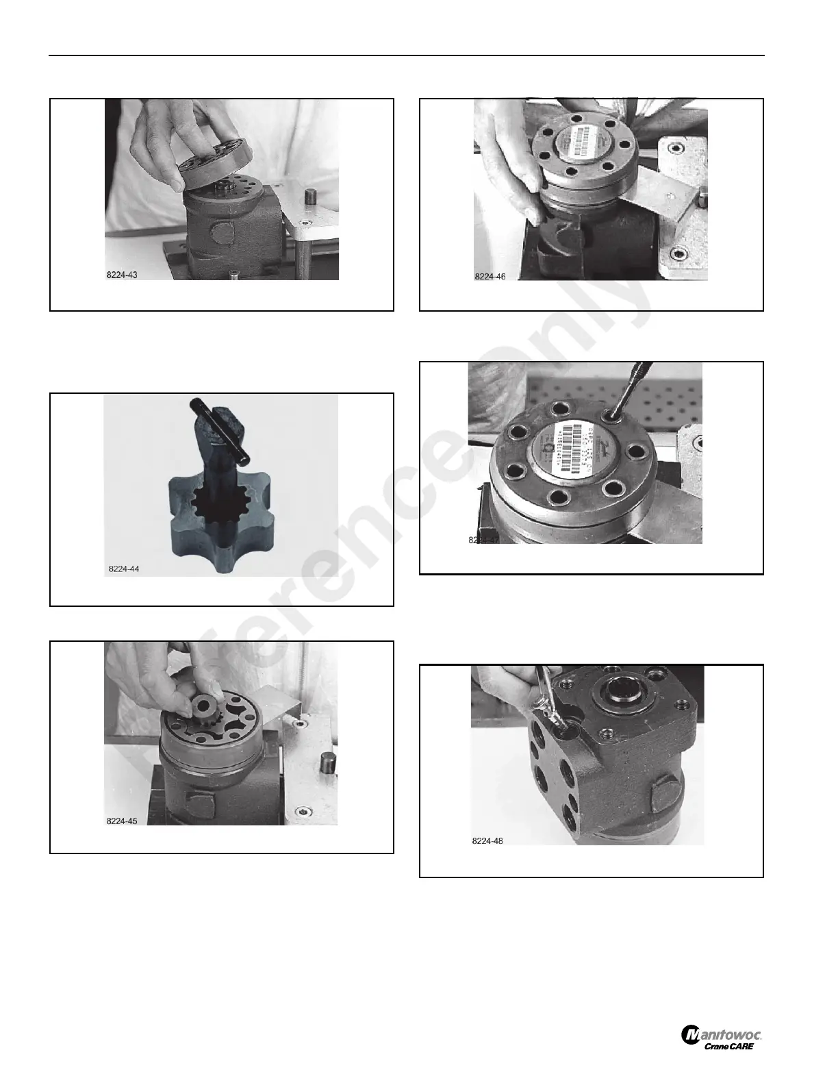
25. Fit the gearwheel (rotor) and cardan shaft so that a tooth
base in the rotor is positioned in relation to the shaft slot
as shown. Turn the gear rim so that the seven through
holes match the holes in the housing.
26. Fit the spacer, if any.
27. Place the end cover in position.
28. Fit the special screw with washer and place it in the hole
shown.
29. Fit the six screws with washers and insert them. Cross-
tighten all the screws with a torque of 30 ±6 Nm (265.5 ±
53 lb in).
30. Install the piston and spring (Figure 10-58).
31. Screw in the setting screw with an 8 mm Allen wrench.
Make the pressure setting on a panel or the vehicle.
Reference Only
 Loading...


