GROVE Published 1-20-2017, Control# 483-02 4-17
CD5515-2/YB5515-2 SERVICE MANUAL HYDRAULIC SYSTEM
3. Start the engine.
4. Ensure the boom is all the way down. Activate the boom
down function at full engine throttle. The pressure gauge
should read 289.57 +/- 3.45 bar (4200 +/- 50 psi).
5. If pressure reading is correct:
a. Shut off the engine, and disconnect the pressure
gauge.
b. Replace the cap nut on the load sense relief valve.
c. Set the pressure on the load sense relief valve, refer
to Load Sense Relief Valve Pressure Setting.
6. If pressure reading is incorrect:
a. Remove the bolt on the suction hose split flange by
the compensator set screw (5, Figure 4-7).
b. Loosen the set screw from the pump compensator
valve (3, Figure 4-7). A 4 mm hex wrench is
required for the set screw.
c. While engaging the boom down function with the
engine at full throttle, adjust the pump max pressure
setting by turning the compensator adjusting screw
(2, Figure 4-7) until 289.58 ± 3.45 bar (4200 ± 50
psi) pressure is obtained on the gauge; clockwise
increases pressure, counterclockwise reduces the
pressure. A 6 mm hex wrench is required for the
adjusting screw.
d. Tighten compensator set screw.
e. Install and tighten the split flange bolt.
f. Shut off the engine, and disconnect the pressure
gauge.
Set the pressure on the load sense relief valve, refer to Load
Sense Relief Valve Pressure Setting
Load Sense Relief Valve Pressure Setting
NOTE: Always set the pressures on the pump
compensator and load sense relief valves together.
1. Install a 0 - 344.73 bar (0-5000 psi) pressure gauge on
the load sense test port (2, Figure 4-6) located on the
front outrigger manifold.
2. Start the engine.
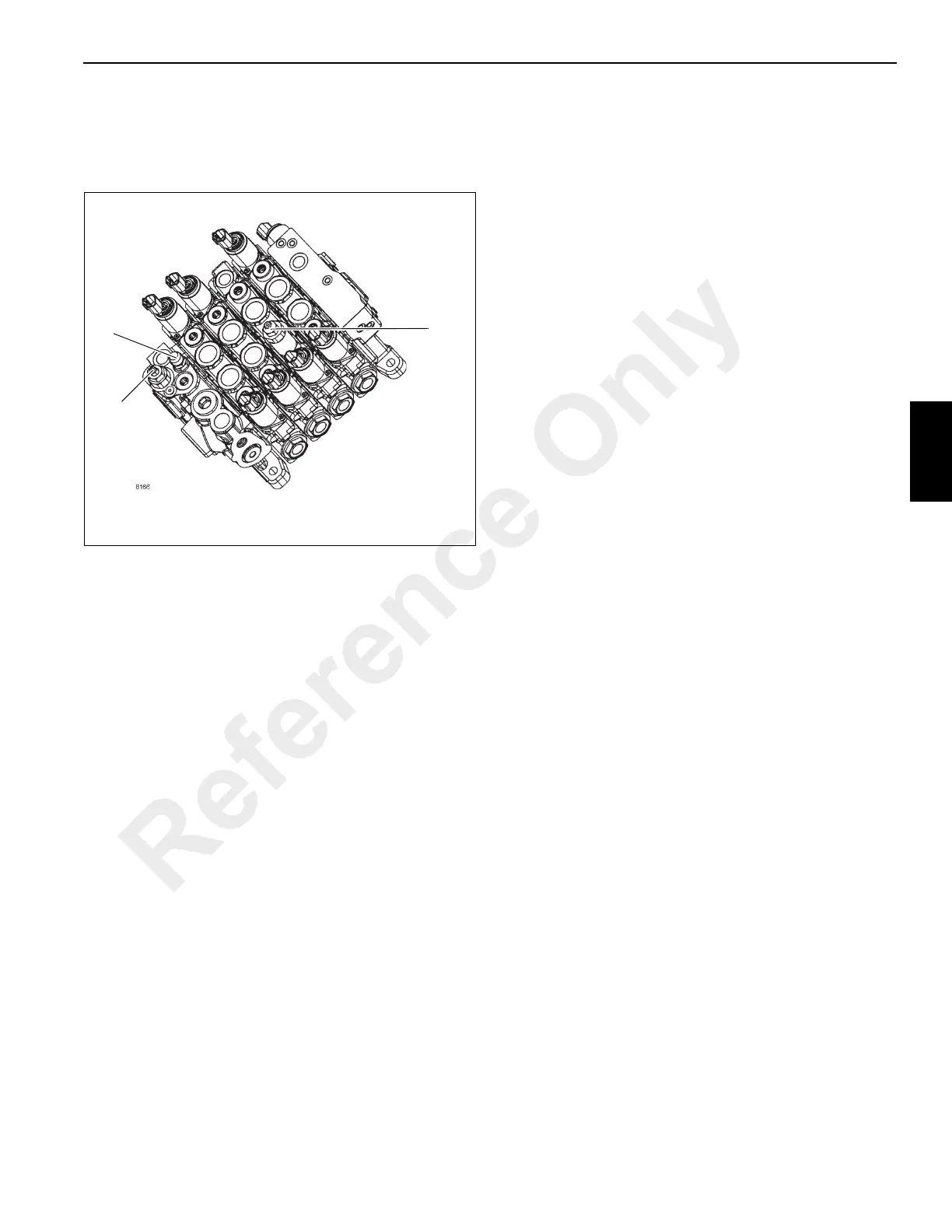
3. Loosen the jam nut on the relief valve (1, Figure 4-8). A
19 mm open end wrench is required for the jam nut.
4. Ensure the boom is all the way down. Activate the boom
down function at full engine throttle, adjust the load
sense relief setting by turning the relief valve adjusting
screw (1, Figure 4-8) until 258.55 ± 3.45 bar (3750 ± 50
psi) pressure is obtained on the pressure gauge;
clockwise increases pressure, counterclockwise
reduces the pressure. A 4 mm hex wrench is required for
the adjusting screw.
5. Tighten the jam nut on the load sense relief valve.
6. Shut the engine off and disconnect the pressure gauge.
7. Set the pressure on the priority flow load sense valve,
refer to Priority Flow Load Sense Relief and
Accumulator Relief Setting, page 4-17.
Priority Flow Load Sense Relief and Accumulator
Relief Setting
1. Install a 0 - 344.73 bar (0-5000 psi) pressure gauge on
the G1 port (1, Figure 4-9) located on the brake/steering
manifold.
2. With the park brake on start the engine. Set crane up on
a level surface with outrigger jacks fully extended.
3. Remove the cap nut on the priority flow load sense relief
valve (2, Figure 4-8) located on the main control valve.
A 18 mm wrench is required for the cap nut. Turn
steering wheel all the way to one side until the steer
cylinder bottoms out while another person adjusts the
priority flow load sense relief setting by turning the relief
valve adjusting screw (2, Figure 4-8) until 172.37 ± 3.45
bar (2500 ± 50 psi) is obtained on the pressure gauge;
clockwise increases pressure, counterclockwise
reduces the pressure. A 3mm hex wrench is required for
the adjusting screw.
4. Replace the cap nut on the priority flow load sense relief
valve.
Reference Only
 Loading...


