28
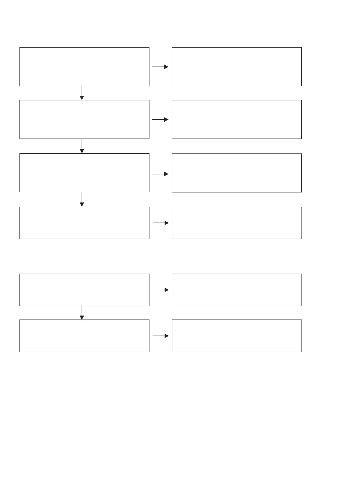
Check the power supply voltage.
Check the VP (+36V)output.
+36V DC (switched) Voltage is O.K.?
・
[CN21] 19pin
Check the power supply voltage.
Check the VDD(+5V) output.
+5V DC (switched) Voltage is O.K.?
・
[CN21] 18pin
POWER PWB
・
[IC92] 1pin input
Check Parts and Soldering and Other Circuits.
If abnormality is not found, [IC92] is replaced.
2. FRONT PWB
2.1. FL TUBE dosen't light
2.2. Remotecontrol is not accepted.
Check the lament voltage.
Check the FIP1
~
FIP2(3.3V) output.
3.3V DC (switched) Voltage is O.K.?
・
[FL51] 1pin,42pin
Check the parts voltage.
TRANSF PWB
・
[T901] 1pin-2pin
If abnormality is found, [T901] is replaced.
POWER PWB
・
[Q901] input
Check Parts and Soldering and Other Circuits.
If abnormality is not found, [Q901] is replaced.
N.G.
N.G.
N.G.
O.K.
O.K.
Check the control waveform.
VFD-DI, VFD-CLK, VFD-CE, VFD-POWER
・
[CN21] 9pin,10pin,11pin,12pin
Check parts and soldering.
MAIN PWB
・
[IC21] 18pin,19pin,20pin,68pin
If abnormality is not found, [FL51] is replaced.
N.G.
O.K.
Check the power supply voltage.
Check the FST(+5V) output.
・
[CN21] pin17
Check the [Q902] collector input.
Check Parts and Soldering and Other Circuits.
If abnormality is not found, [Q902] is replaced.
N.G.
O.K.
Check the output waveform.
When the button of remote control is pushed, is the
pulse output?
・
[CN21] 15pin
Replace the [RS51].
N.G.