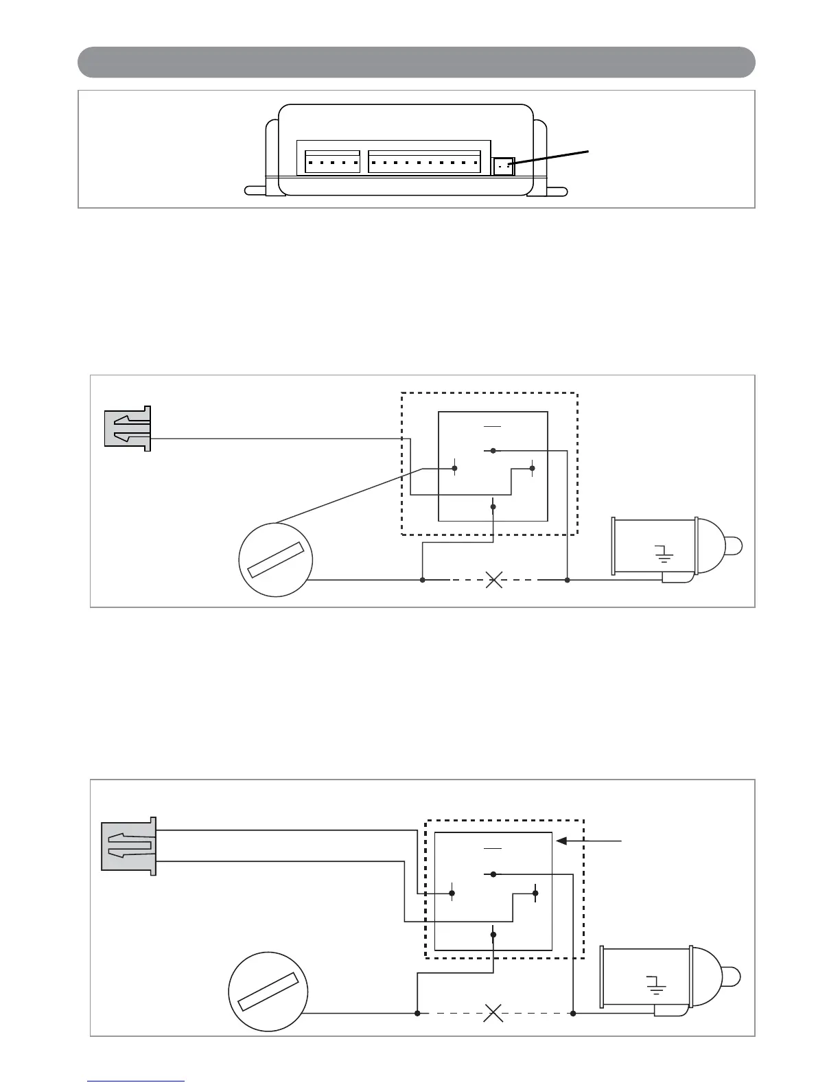
HC1: Starter Disable Wiring Using a Common Relay
Using the wiring information and diagram below, connect the optional starter disable relay as follows:
A. Locate the “Start Only Wire” coming from the ignition key switch and cut it.
B. Connect the ends of the cut start wire to pins #30 and 87a of the relay pack.
C. Connect the single orange wire harness supplied (with 2-pin orange connector) to pin #85 on the relay.
D. Connect pin #86 to the true ignition switched wire from the ignition key.
To test the starter disable system refer to the starter disable testing procedures located in the testing section of
this manual.
Orange Wire
(Ground when Armed Alarm Output)
Connector
(Supplied)
87
87a
86
85
30
"ACC" "START"
"OFF" "IGN"
Cut Black Black
Starter
12
P7
Plug-In Ports (continued)
HC1: Starter Disable Wiring Using ALA-RPS Relay Pack
Using the wiring information and diagram below, connect the optional starter disable relay as follows:
A. Locate the “Start Only Wire” coming from the ignition key switch and cut it.
B. Connect the ends of the cut start wire to the black wires coming from the ALA-RPS relay pack.
C. Plug in the orange 2-pin plug into the orange socket located on the alarm module.
To test the starter disable system refer to the starter disable testing procedures located in the testing section of
this manual.
87
87a
86
85
30
"ACC" "START"
"OFF" "ON"
Cut Black
Starter
ALA-RPS
Relay Pack
(Ign. Switched +12VDC)
Black Wire
(Ground when Armed Alarm Output)
Black
X4-IM.qxp 3/6/08 10:53 AM Page 12


 To Next Page