HC2: White 5-Pin Power Harness
6
Wiring (continued)
Black/White Wire: (-) Dome Light Supervision Output
The Black/White wire provides a low current (300mA) grounded output that can be used to activate the vehicle’s
interior lighting system when the security system is disarmed. In some vehicles, an additional relay may be
required for proper installation (See Optional Accessory Connection for proper wiring).
Vacant Socket: Provides +12VDC for Relay Connection
See Optional Accessory Connection for proper wiring.
Black Wire: Chassis Ground
This is main ground connection of the alarm module. Make this connection to a solid section of the vehicle
chasis. Do not connect this wire to any existing ground wires supplied by the factory wire loom, make the
connection to the vehicle’s chasis directly.
Yellow Wire: +12VDC Ignition Input
Connect the Yellow wire to a +12 volt wire that is switched on and off by the ignition key. The correct wire will
indicate +12 volts when the ignition key is in the on and start positions. Do not connect the yellow wire to the
“ACC” wire coming from the ignition switch.
Red Wire: +12VDC Battery Input
Connect the Red wire directly to the (+) battery post for best operation of the alarm system.
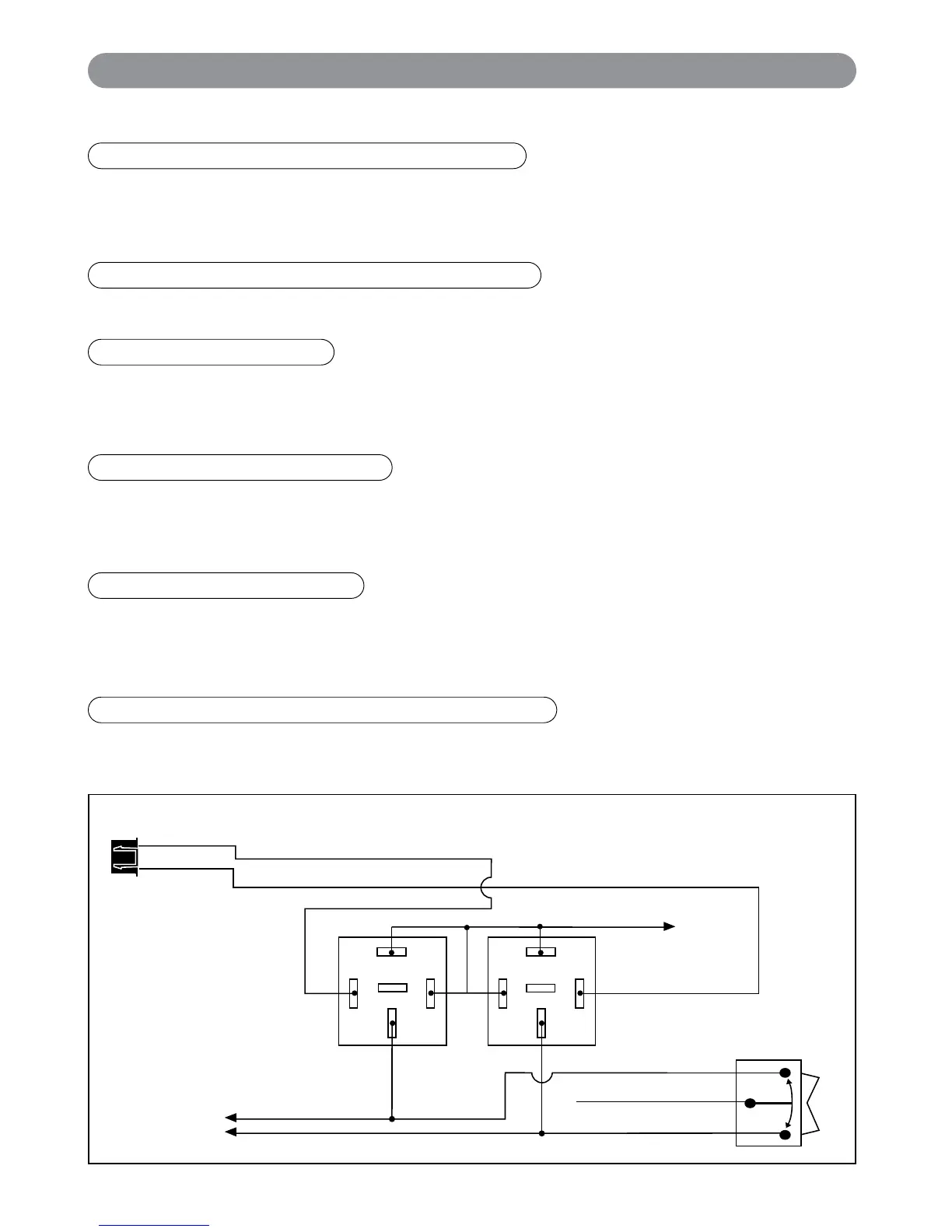
HC3: Black 3-Pin Door Lock Harness
Blue Wire: Connect to Unlock
Green Wire: Connect to Lock
Lock Control
Switch
Black 3-Pin
Mini Connector
87
87A
85
86
30
87
87A
85
86
30
To Fused +12v
If the door lock control system on the vehicle is (-) type, connect the Blue wire to the unlock wire from the door
lock switch .
Blue Wire: (-) Door Unlock
X4-IM.qxp 3/6/08 10:53 AM Page 6