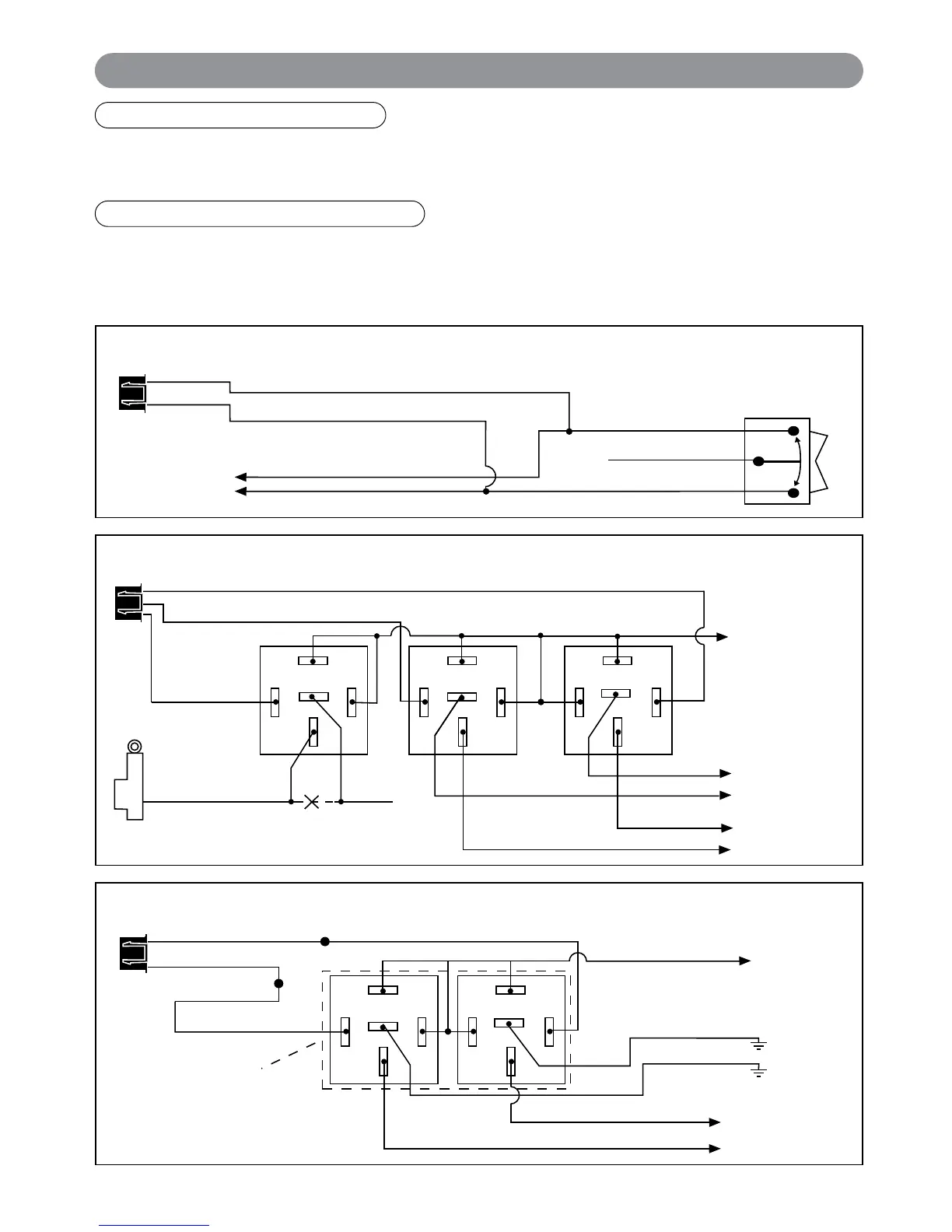
EasyManua.ls Logo

Marksman X4 - Parking Light Flash Indicators; Siren;Horn Chirp Indicators; System Characteristics

Marksman X4
20 pages
Print Icon
To Next Page IconTo Next Page
To Previous Page IconTo Previous Page
Loading...
7
Wiring (continued)
3 Wire Ground Trigger Door Lock System
(
-
) Lock Out
Ground Input
(
-
) Unlock Out
To Door Lock
Control Relays
Lock Control
Switch
Blue Wire: Connect to Unlock
Green Wire: Connect to Lock
Black 3-Pin
Mini Connector
Unlock Driver's Door First Wiring for 5-Wire Ground at Rest Door Locking Systems
87
87A
85
86
30
87
87A
85
86
30
To +12 Volts
(Battery +)
To Power
Lock Switch
To Power
Lock Motors
Lock
Lock
Unlock
Unlock
87
87A
85
86
30
+ Unlock
Cut
Driver's
Door Motor
Green Wire
Blue Wire
Light Blue Wire
Newly Installed Power Door Lock Motors
87
87A
85
86
30
87
87A
85
86
30
To +12 Volts
(Battery +)
To Ground
To Newly
Installed Power
Door Lock Motors
White Wire
Brown Wire
Green Wire: Lock
Blue Wire: Unlock
Violet Wire
ALA-DL1
Relay Pack
Red Wire: Lock
Black Wire: Unlock
Black 3-Pin Connector
Green Wire
Blue Wire
Note: Orange wire from ALA-DL1
must be connected to +12V
Green Wire: (-) Door Lock Control
Light Blue Wire: (-) 2nd Unlock Output
If the door lock control system on the vehicle is (-) type, connect the Green wire to the lock wire from the door
lock switch .
Driver’s Door Priority 2nd Unlock Output:
The Light Blue wire provides a second (-) unlock output to unlock the passenger’s doors. Follow the diagrams
on pages 6-9 for proper connection.
X4-IM.qxp 3/6/08 10:53 AM Page 7

Other manuals for Marksman X4

Related product manuals