User Manual 7
7. Tighten the rigging clamps securely to the structure.
8. Verify that there are no combustible materials or surfaces to be illuminated within 1 meter of the fixture,
and that there are no flammable materials nearby.
Connecting the serial link
Tips for building a serial link
1. Use shielded twisted-pair cable designed for RS-485 devices. Standard microphone cable cannot
transmit control data reliably over long runs; use only cable designed for RS-485 applications. 24 AWG
cable is suitable for runs up to 300 meters (1000 ft). Heavier gauge cable and/or an amplifier is recom-
mended for longer runs.
2. Never use a “Y” connector to split the link. To split the serial link into branches use a splitter such
as the Martin 4-Channel Opto-Isolated RS-485 Splitter/Amplifier.
3. Do not overload the link. Up to 32 devices may be connected on a serial link.
4. Terminate the link by installing a termination plug in the output socket of the last fixture on the link.
The termination plug, which is simply a male XLR connector with a 120 ohm, 0.25 watt resistor sol-
dered between pins 2 and 3, “soaks up” the control signal so it does not reflect back down the link and
cause interference. If a splitter is used, terminate each branch of the link.
Connecting fixtures
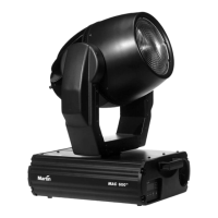
The MAC 600/E has locking 3-pin data input and output sockets that can be configured for use with either DMX or Martin
Protocol controllers. The default pin-out is configured to the DMX-512 standard, i.e., pin 1 to shield, pin 2 to signal (-) and
pin 3 to signal (+).
1. Connect the controller’s data output to the MAC 600/E’s data input. For a
• DMX controller with 5-pin output: use a cable with 5-pin male and 3-pin female connectors such as
P/N 11820005. Pins 4 and 5 are not used.
• DMX controller with 3-pin output: use a cable with 3-pin male and female connectors such as the one
supplied.
• Martin RS-485 Protocol controller: use a phase-reversing cable, such as P/N 11820006, with 3-pin
male and female connectors or reconfigure the XLR output.
2. Continue the link: connect the output of the fixture closest to the controller to the input of the next fix-
ture. Use a phase-reversing cable when connecting a DMX-standard (pin 3 +) device to a Martin-stan-
dard (pin 3 -) device.
3. Insert a male 120 Ω XLR termination plug in the output of the last fixture on the link.
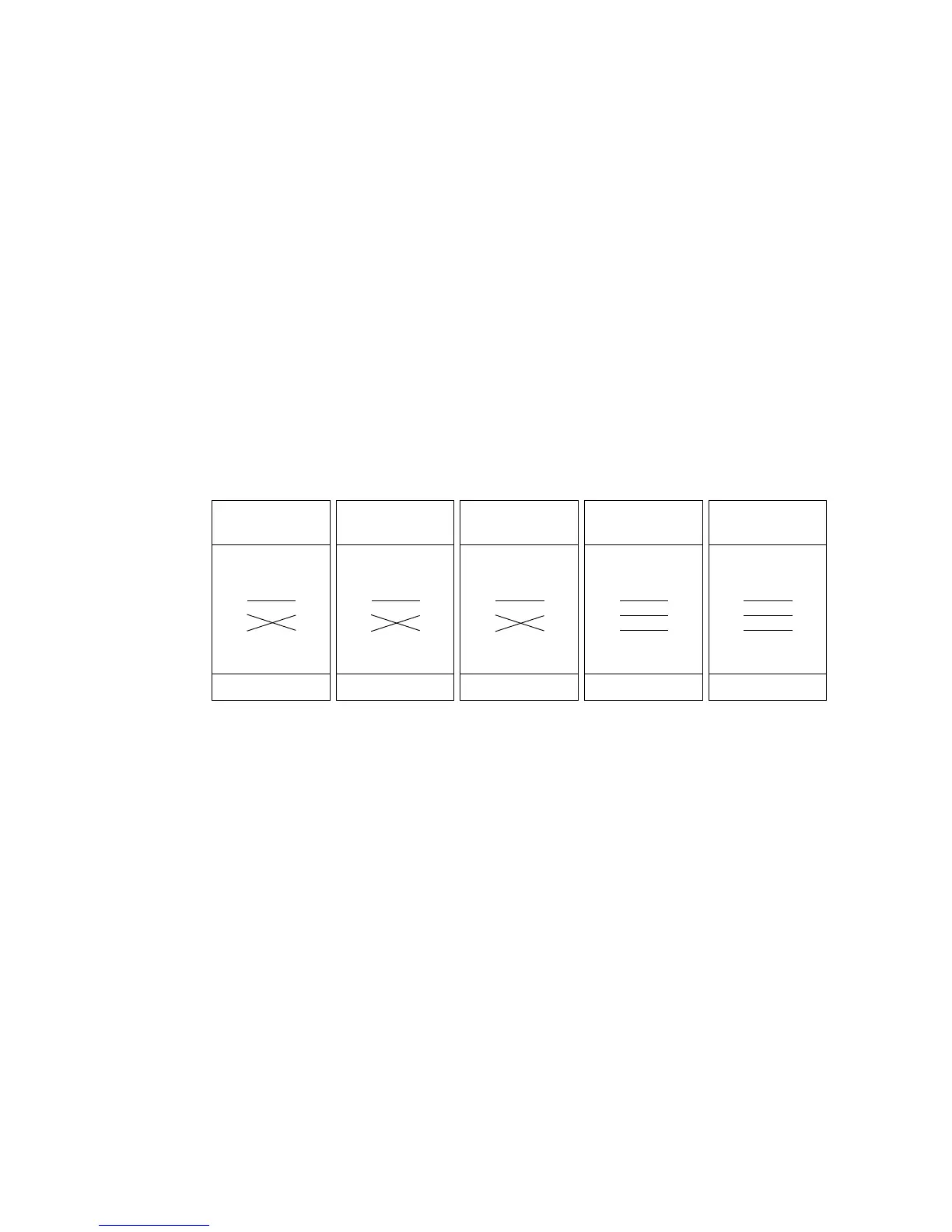
Phase-Reversing
Cable
Male Female
1
2
3
1
2
3
3-pin to 3-pin
Connections
P/N 11820006
Phase-Reversing
Cable
Male Female
1
2
3
1
2
3
4
5
3-pin to 5-pin
Connections
P/N 11820002
Phase-Reversing
Cable
Male Female
1
2
3
4
5
1
2
3
5-pin to 3-pin
Connections
P/N 11820003
Straight
Cable
Male Female
1
2
3
4
5
1
2
3
5-pin to 3-pin
Connections
P/N 11820005
Straight
Cable
Male Female
1
2
3
1
2
3
4
5
3-pin to 5-pin
Connections
P/N 11820004