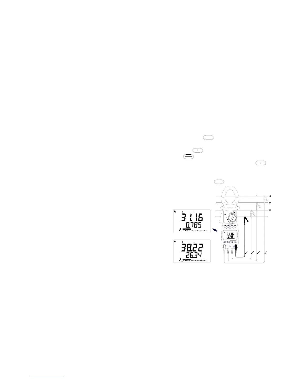
1. Refer to Table 3, connect yellow test lead, green test lead, red test
lead to every phase live wire of the three-phase circuit and V1 jack,
V2 jack, V3 jack of the meter respectively, connect black test lead
to zero conductor of the circuit and COM jack of the meter.
2. Turn the selector to Φ1 at first ( to first phase measurement ),
hook the clamp jaw around the first phase conductor of the tested
circuit, press
kW / PF
button to measure Active Power (kW) and
Power Factor (PF). the measured value are shown in the LCD then
press button to sum power parameter of this phase; press
kVAr
kVA
button again to measure Apparent Power and Reactive
Power, after the result is shown in the LCD, press button
to sum power parameter of this phase. So power parameter
measurement is completed in the first phase. If you need save the
result, you can press
SAVE
button to do it. ( Figure 12 )
( Figure 12.The First Phase Power Measurements )
- 20 -
AC
MEM
MEM
PF
1
604020
00
20 6040
00
kVAr
kVA
10080
10080
kVAr
kVA
TIME
kWh
20
MAX
1
V2
40 60 8 0 10 0
SAVE
COM
MIN
kW
V3
CLEAR
RS232
A
kW / PF
00
MEM
AC
PF
V1
V / Hz
AC
1
kW
600V
CAT.III
MAX
P
-
3
EX
2
OFF
HOLD
OFF
1
1000A
600kW
MAX
Ture RMS
MR
W
AUTO RANGE
GreenRed
Black
Yellow
Tested conductor
1
2
Earth wire
3