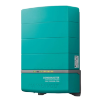
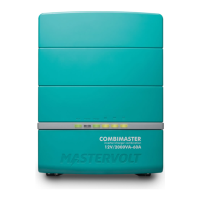
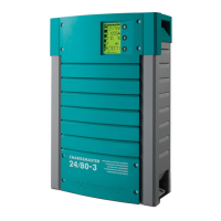
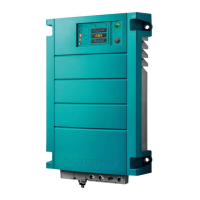
CombiMaster 120V Series –
User and Installation Manual
7.2 Materials needed
Description (n = number of parallel units)
Multiple units of the same type and model
Temperature sensor with cable and plug
DC + cables of equal gauge and length
DC – cables of equal gauge and length
AC input cables of equal gauge and length
AC output cables of equal gauge and length
CZone drop cable (for a CZone network only)
MasterBus Terminator (for a new MasterBus network
only)
MasterBus cables between units*
Cable Strain Relief Bracket*
* Mastervolt offers various cable kits that contain this item. See the Mastervolt website for details.
7.3 Preparations
•
Make sure that all power sources (AC and DC) are turned off.
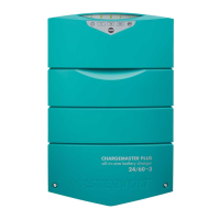
• Make sure the "On/Charge only"-switch position is "Charge only" (
on all units.
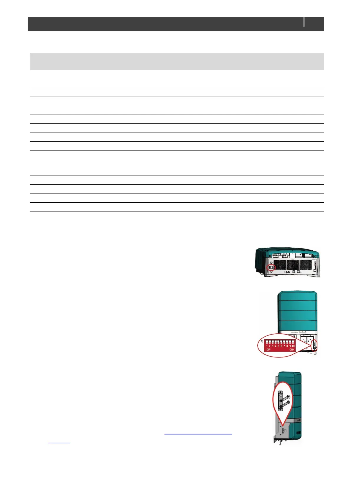
• Remove the front cover plate by loosening the two screws at the
bottom, and make sure that all DIP switches are off on all units.
• By default, the Neutral (N) output automatically connects to the
Safety Ground (PE) when the CombiMaster Inverter/Charger is
disconnected from an external AC source.
See also section AC safety grounding on page 17.
Refer to the related Technical Bulletin for more information on multi-
unit configuration with single point neutral to ground bonding.
Technical Bulletins are published on the portal on the Mastervolt
website.