CombiMaster 120V Series –
User and Installation Manual
4.5.3 AC safety grounding
If installed in a head, galley, machinery space, or on a weather deck, Ground Fault Circuit
Interrupters (GFCIs) of 30mA must be integrated in the AC input and AC output of the
CombiMaster Inverter/Charger.
An Equipment Leakage Circuit Interrupter (ELCI) shall be installed within 10" of the shore
power inlet.
Refer to locally applicable regulations regarding grounding of autonomous power systems.
Neutral to Ground Bonding
To ensure a correct operation of Ground Fault Circuit Interrupters (GFCIs), the AC output Neutral (N)
connects to the Safety Ground (PE) –the so called neutral to ground bonding– when the AC input of the
CombiMaster Inverter/Charger is disconnected from an external AC source. This default setting of the
grounding system works well in most situations. However, depending on national or local regulations,
neutral to ground bonding may not be allowed. In that case, this automatic switching feature must be
disabled.
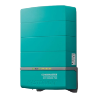
• Models 1500W, 2000W, 3000W
The selection of enabling/disabling automatic
neutral to ground bonding in inverter mode, is
done by positioning the grounding system
jumper (located on the left side of the
CombiMaster Inverter/Charger).
Default
setting
To disable this
automatic
bonding, move
the jumper to
position X-N.
Bonding
disabled
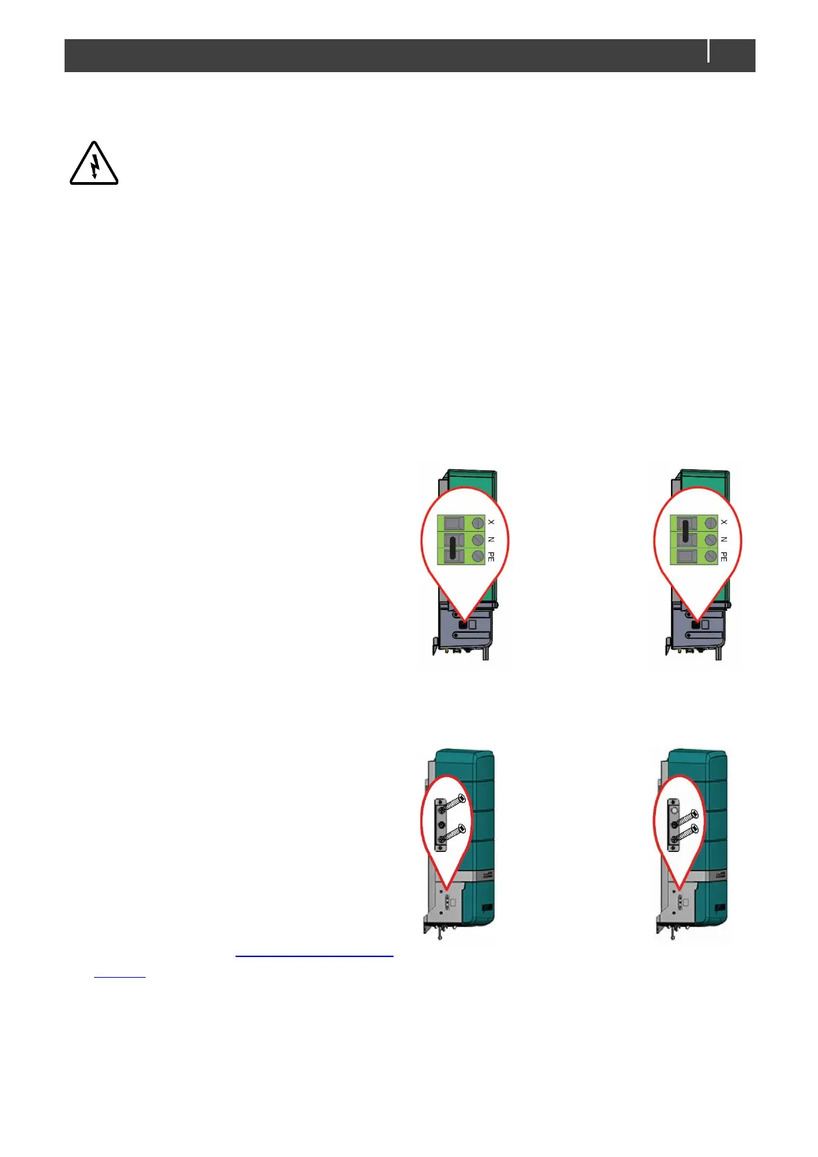
• Models 3500W, 4500W, 5000W
The selection of enabling/disabling automatic
neutral to ground bonding in inverter mode is
done by positioning the two M3x8 screws
(located on the left side of the CombiMaster
Inverter/Charger, behind a removable plate).
For a multi-unit configuration with single point
neutral to ground bonding, please refer to the
related Technical Bulletin. Technical Bulletins
are published on the portal on the Mastervolt
website.
Default
setting
To disable this
automatic
bonding, move
the upper screw
to the middle.
Bonding
disabled