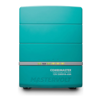
– User and Installation Manual
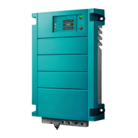
3.1.2 Models 3500W, 4500W, 5000W
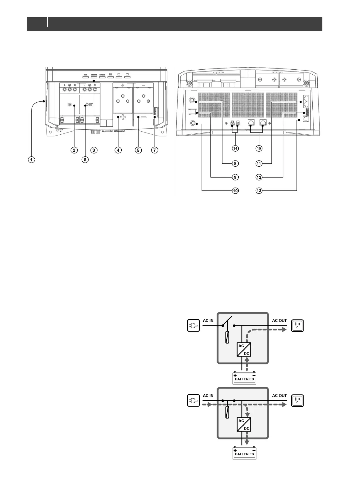
Front side with open connection compartment
Figure 3. Connections for models with product code: 35513500, 35523500, 35524500, 35545000.
1 Neutral-ground bonding
2 AC input
3 Status LEDs
4 5/16" Positive battery terminal
5 5/16" Negative battery terminal
6 AC output
7 DIP switches
8 Resettable thermal breaker (50A)
9 "On/Charge only"-switch
10 5/16" Ground stud
11 CZone/MasterBus connection
12 Accessories connector
13 Temperature sensor connection
14 Current sharing (parallel unit configuration)
15 Cluster communication ports (multi-unit
configuration)
For information on multi-unit configurations, see chapter 7.
3.2 Operating modes
•
Inverter mode: When there is no external AC
power available, the inverter provides AC power
on the AC output. If energy saving mode is
enabled, battery power consumption will be
reduced when there is no load on AC OUT.
Please note that some electronic loads such as
wifi routers, satellite receivers, or digital clocks
are most likely not to work in this mode.
• Charger mode: When external AC power is
available on the AC input, the battery will be
charged and the AC output is supplied by the
external power.