43
5.18 IR SENSOR REPLACEMENT
CHAPTER 5: PART REPLACEMENT GUIDE
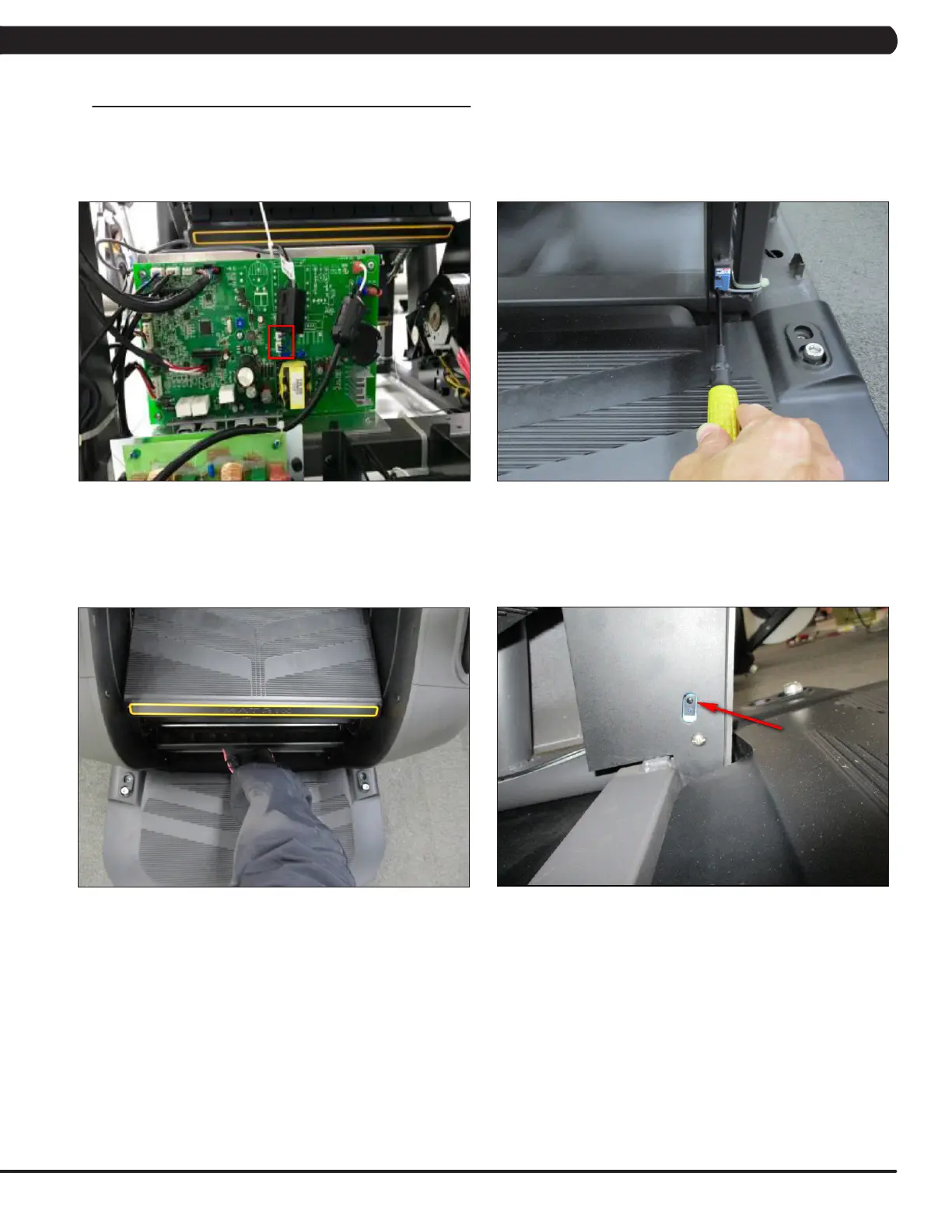
FIGURE A FIGURE B
1) Turn off the power and disconnect the cord from the machine.
2) Remove the service cover as outlined in Section 5.1.
3) Remove the side covers as outlined in Section 5.2.
4) Remove the IR sensor cable from the LCB, and cut any wire ties holding the cable to the LCB (Figure A).
5) Remove the 2 screws holding the IR sensor to the frame (Figure B), and cut any wire ties holding the cable to the frame.
6) Reverse Steps 1-5 to install a new IR sensor. NOTE: When re-installing the IR sensor, make sure that the IR sensor with black wire (2
pin) is on the left (transmission) and the other IR sensor with gray wire (3 pin) is on the right (receiver).
7) Once the IR sensor is installed, Press the GO key and begin using the machine. Put your foot in the middle of the IR sensors (transmission
& receiver) to test whether the sensors are working enough to stop machine (Figure C). NOTE: The sensor has an eye. The eyes of two
sensors should be mounted facing each other so that interrupting their path will stop the machine (Figure D).
8) Test the Climb Mill for function as outlined in Section 5.19.
FIGURE C FIGURE D
 Loading...