37
5.13 BRAKE REPLACEMENT
1) Turn off the power and disconnect the cord from the machine.
2) Turn the brake lever to the right to lock the stairs and prevent movement that could cause injury.
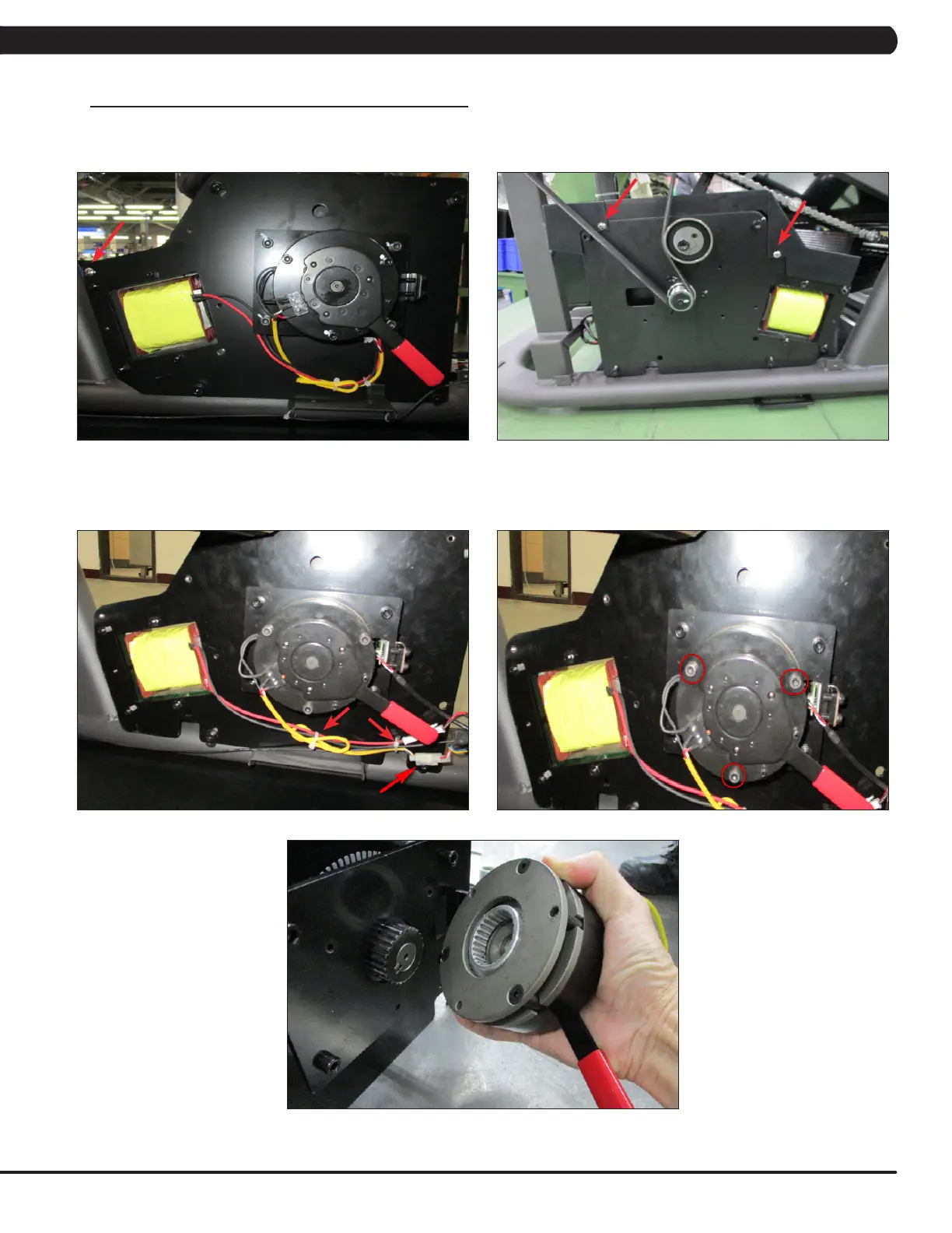
3) Remove the 3 screws that connect the top cover to the drive set and remove it (Figure A & B).
4) Disconnect the brake wire connection and 2 cable ties holding the brake and brake wire to the plate (Figure C).
5) Remove the 3 screws holding the brake to the drive set (Figure D) and remove the assembly (Figure E). NOTE: BEFORE REMOVING THE
BRAKE, BLOCK THE STAIRS FROM ROTATING (PLACE A BLOCK UNDER THE BOTTOM STAIR) TO PREVENT INJURY.
6) Reverse Steps 1-5 to install a new brake. Tighten the bolts removed in Step 5 to 15 N-m (Figure D).
7) Test the Climb Mill for function as outlined in Section 5.19.
FIGURE C
FIGURE E
CHAPTER 5: PART REPLACEMENT GUIDE
FIGURE D
FIGURE BFIGURE A
 Loading...