Hi‐TCentralizedcontroller
16
3.5 SECONDMAINPAGE
From the home page, touching the arrow icon to navigate to the next screen, you go to a second screen showing all of the
detectionscarriedoutbythetemperaturesensorsandhumiditysensorsinthesystem.
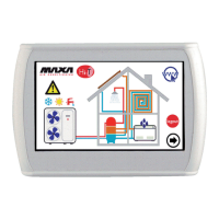
Figure 15. Second Main page.
Referringtothefigureabove:
• Field1indicatesthezonetowhichyouarereferring;applyingpressureonit,youswitchtothenextzone.
• Field2indicatesthefancoilwhichisreferencedwithinthezoneselectedfromthefield1;pressingonittheindex
ofthe
selected zoneprogresses in a cyclic manner,giving away all the fan coilunitsinthearea. For each fan coil is shown the
detectedairtemperature.Theseindicationsappearonlyiftherearefancoilsconfiguredinthesystem.
• Field3indicatesthechillerwhichit
refers;bypressingonit,youprogresstothenextchillerinthenetwork.Foreachchiller
shown, you see the readings on thetemperatureof the water inlet and outlet of the chiller and on the air temperature
measuredbytheprobesonboard.
• Field4showstheambient
temperatureandtherelativehumiditymeasuredbythesensorsintegratedintheHi‐Tpanel.
• Field 5 indicates the presence of the solar system; then the indication on the temperature of the solar panels is shown.
Theseindicationsappearonlyifinthesystemisconfiguredasolarpanel.
• Field 6 shows the enabling of the production of domestic hot water related to the chiller selected from field 3 . It also
indicatesthetemperatureofthedomestichotwaterproduction.
• Field 7 indicates the presence of a storage tank connected to the chiller selected from field 3.
It also indicates the
temperatureofthedomestichotwaterproduction.
• Field8indicatesthepresenceofradiantfloor;thisfieldisconnectedtotheenablingofthefunctionofdoubleset‐point.
Inthecaseofprobesinerrorornotproperlyconfiguredandconnected,itappears
theindicationoferror.
NOTE:Thepresenceofaccumulationandthesanitarymodeareherereferredtothefactthatinthenetworkispresentaheatpump
inwhichthesanitarymodeisenabled.
5
3 7
4
1
2
6
8