45
11921 Slauson Ave. Santa Fe Springs, CA. 90670 (800) 227-4116 FAX (888) 771-7713
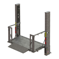
5. Position pump and battery box frame on
vehicle frame cross members (FIG. 45-1).
Ensure vent holes on back of the battery
box are not obstructed or covered (FIG.
45-1). Weld pump and battery box frame
to cross members as shown in FIG. 45-1.
ALIGNING PUMP & BATTERY BOX FRAME
TO WELD ON CROSS MEMBERS
FIG. 45-1
3/16”
3/16”
WELD PUMP & BATTERY FRAME,
ALONG WIDTH OF FRAME ANGLE, TO
EVERY CROSS MEMBER IN CONTACT
WITH FRAME ANGLE
CROSS MEMBERS
CROSS MEMBERS
STEP 7 - ATTACH PUMP & BATTERY BOX FRAME TO
VEHICLE - Continued
NOTE: Any methods not shown in this section, for welding mounting brackets to
cross members, must be approved by body or trailer manufacturer.
Explosive hydrogen gas from charging batteries can accumulate in battery box if
not vented from the box. To prevent hydrogen gas from accumulating, ensure the
3 ventilation holes in battery box are not plugged or covered.
WARNING
!
 Loading...