11921 Slauson Ave. Santa Fe Springs, CA. 90670 (800) 227-4116 FAX (888) 771-7713
25
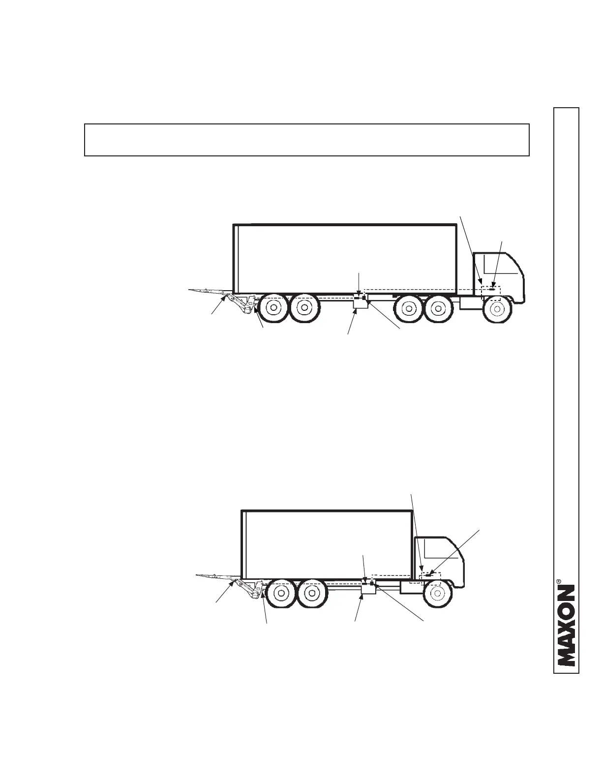
STEP 3 - ATTACH OPTIONAL BATTERY BOX & FRAME
TO VEHICLE (IF EQUIPPED)
1. Liftgate and optional
battery box are typically
installed on trailers as
shown in FIG. 25-1 and
on trucks as shown in
FIG. 25-2. See the fol-
lowing page for battery
and cable connections.
LIFTGATE
OPTIONAL
BATTERY BOX,
TYPICAL LOCATION
RECOMMENDED LIFTGATE & OPTIONAL BATTERY BOX
INSTALLATION ON TRAILER
FIG. 25-1
150 AMP CIRCUIT
BREAKER
175 AMP
FUSED CABLE
TRACTOR BATTERIES,
TYPICAL LOCATION
LIFTGATE
LIFTGATE
POWER UNIT
RECOMMENDED LIFTGATE & BATTERY BOX
INSTALLATION ON TRUCK
FIG. 25-2
150 AMP CIRCUIT
BREAKER
RECOMMENDED CONFIGURATION
NOTE: Make sure the Liftgate power unit, and all batteries on the vehicle for the
power unit, are connected correctly to a common chassis ground.
LIFTGATE
POWER UNIT
175 AMP
FUSED CABLE
175 AMP
FUSED CABLE
TRUCK BATTERIES,
TYPICAL LOCATION
OPTIONAL
BATTERY BOX,
TYPICAL LOCATION
150 AMP
CIRCUIT BREAKER