Specifications
Technical Data
IDX 70 User Manual
2-16 mmag | 2022-04 | rel10520
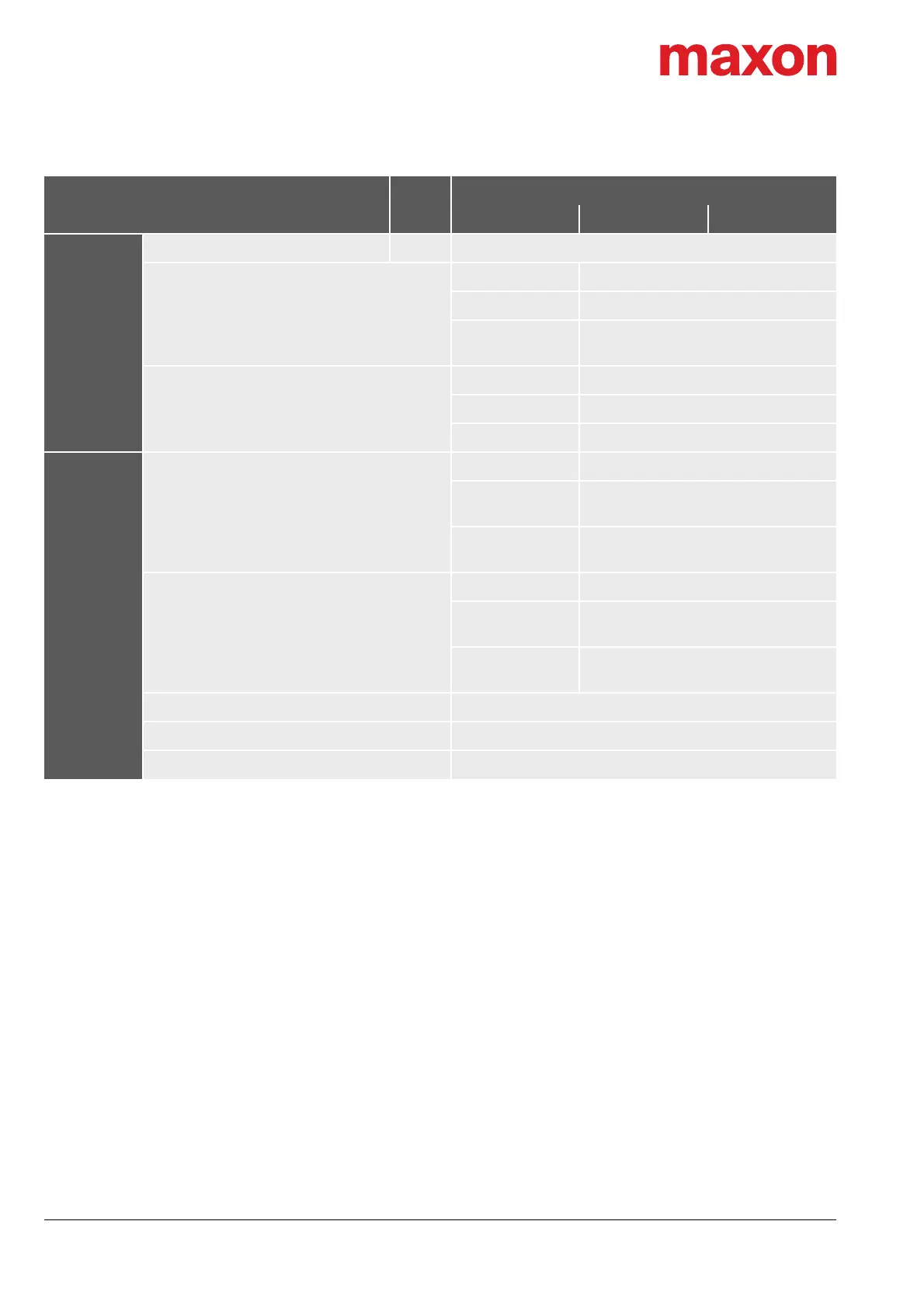
Table 2-5 Technical data
Status
indicators
Device status Operation (green LED) / Error (red LED)
NET status
I/O —
CANopen —
EtherCAT
RUN state (green LED)
Error (red LED)
NET port
I/O —
CANopen —
EtherCAT Link activity (green LED)
Connections
X1 IN
I/O —
CANopen
Bus connector
M8, male, 5 poles, B-coded
EtherCAT
Bus connector
M8, female, 4 poles, A-coded
X2 OUT
I/O —
CANopen
Bus connector
M8, female, 5 poles, B-coded
EtherCAT
Bus connector
M8, female, 4 poles, A-coded
X3 I/O M12, male, 12 poles, A-coded
X4 Supply M23x1, male, 6 poles
X5 USB USB Type micro B, female
[a] Values at nominal speed and ambient temperature T
a
= 40 °C
[b] Values at nominal speed and ambient temperature T
a
= 25 °C
[c] With optional holding brake: the minimal power supply voltage +V
CC
is 24 VDC
[d] If equipped, the inertia of the holding brake (page 2-14) must be added
[e] The stated protection class refers to the motor housing with plugged original connectors and installed shaft sealing. The
adequate shaft sealing must be provided by the customer. Without shaft sealing or with a shaft sealing falling short of
the stated protection class, the device will only support the protection class stated in brackets.
The protective caps fitted on delivery do not provide IP65 protection.
[f] From 40 °C and above 1'000 m MSL (Mean Sea Level), a derating of the stated performance data must be expected.
The maximum achievable operating points must be determined by testing.
[g] Operating altitude in meters above Mean Sea Level, MSL
[h] In addition to the drive’s mechanical data
Parameter Unit
IDX 70 S IDX 70 M IDX 70 L
24 V 48 V 60 V