Mechanical Installation
Alignment and Coupling
IDX 70 User Manual
mmag | 2022-04 | rel10520
3-23
3.4 Alignment and Coupling
The drive’s free shaft end must be connected to the surrounding system by a force-fit, free of play, zero-
backlash coupling.
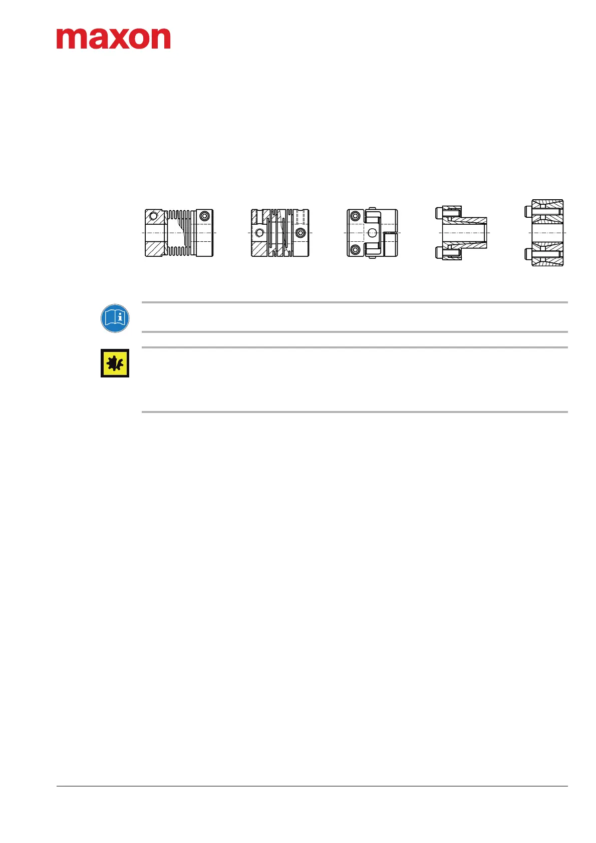
First choices are, for example, metal bellow, collet chucks, or shaft-hub joint coupling. They form a frictional
connection and are capable to transmit the occurring torque. As with all rigid couplings, an adequately accu-
rate radial, axial, and angular alignment of the two connecting shaft ends is essential.
Figure 3-9 Couplings and shaft-hub joints – typically suitable designs (examples)
Check original manufacturer’s specifications
Consult the specifications of the coupling manufacturer prior installation.
Comply with original manufacturer’s specifications and respect permissible loads
• Make sure to not exceed the permissible axial force of 270 N during assembly or disassembly.
• Make sure to align the coupling according to the manufacturer’s specifications.
• Make sure that the axial and radial forces that are going to occur during operation will not exceed the lim-
its stated (
“Mechanical data” on page 2-14).