Electrical Installation
Connections
IDX 70 User Manual
4-32 mmag | 2022-04 | rel10520
4.3.3 EtherCAT IN (X1) and EtherCAT OUT (X2)
Wrong plugging can cause irreversible hardware damage
Even though both EtherCAT sockets are prepared for identical external wiring, make sure to always connect
them as follows.
• For suitable prefab cable assemblies see
Table 4-9 on page 4-27.
• Use EtherCAT IN (X1) as «Input».
• Use EtherCAT OUT (X2) as «Output».
For detailed information see separate document
«IDX Communication Guide».
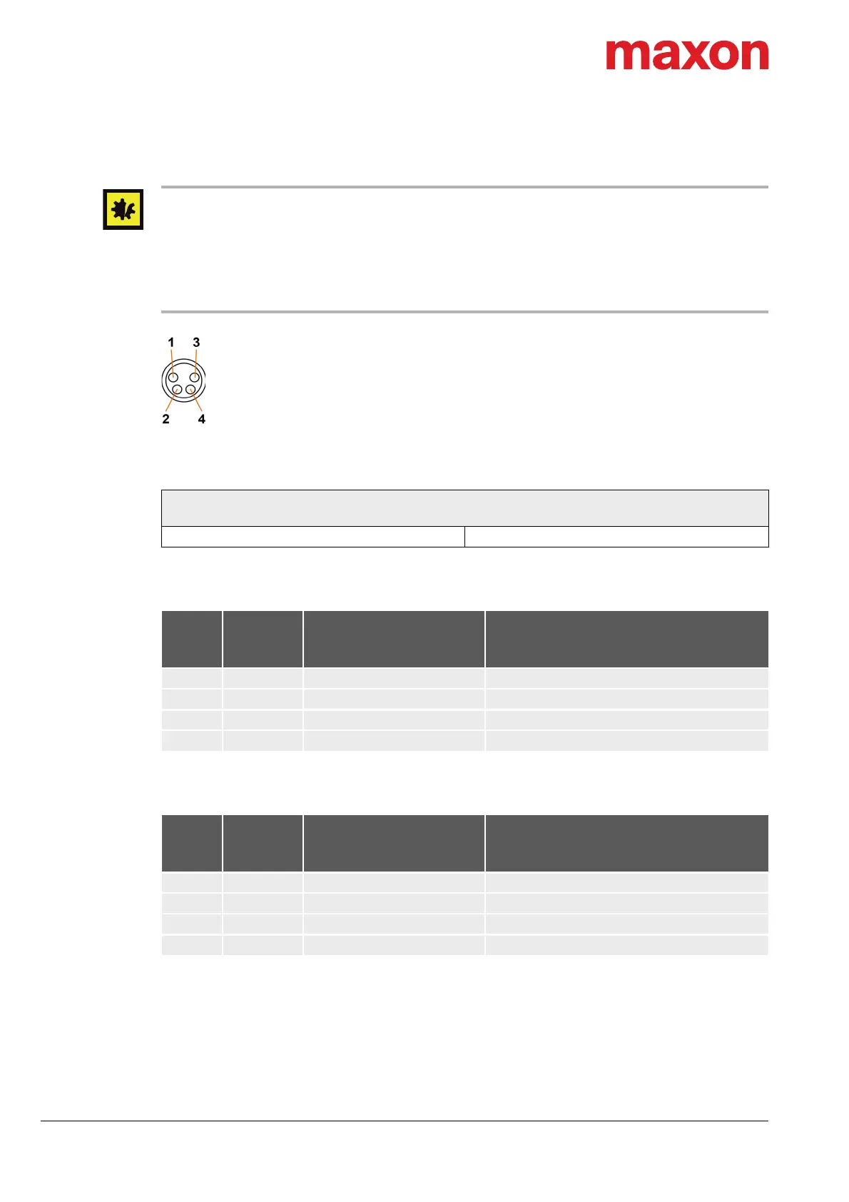
Figure 4-15 EtherCAT IN connector X1 & EtherCAT OUT connector X2
Table 4-15 EtherCAT IN connector X1 & EtherCAT OUT connector X2 – Specification
Table 4-16 EtherCAT IN connector X1 – Pin assignment
Table 4-17 EtherCAT OUT connector X2 – Pin assignment
For suitable prefab cable assemblies see Table 4-9 on page 4-27.
EtherCAT IN connector X1
EtherCAT OUT connector X2
Type M8, female, 4 poles, A-coded
X1
Head A
Prefab
cable
Signal Description
Pin Color
1 yellow IN_TX+ EtherCAT IN transmission data+
2 white IN_RX+ EtherCAT IN receive data+
3 blue IN_RX− EtherCAT IN receive data−
4 orange IN_TX− EtherCAT IN transmission data−
X2
Head A
Prefab
cable
Signal Description
Pin Color
1 yellow OUT_TX+ EtherCAT OUT transmission data+
2 white OUT_RX+ EtherCAT OUT receive data+
3 blue OUT_RX− EtherCAT OUT receive data−
4 orange OUT_TX− EtherCAT OUT transmission data−