Electrical Installation
Connections
IDX 70 User Manual
4-30 mmag | 2022-04 | rel10520
How to read pin assignment tables
• The first column describes both the pin number of the connector and of the matching prefab maxon
cable’s Head A.
• The second column describes the cable core color of the prefab maxon cable.
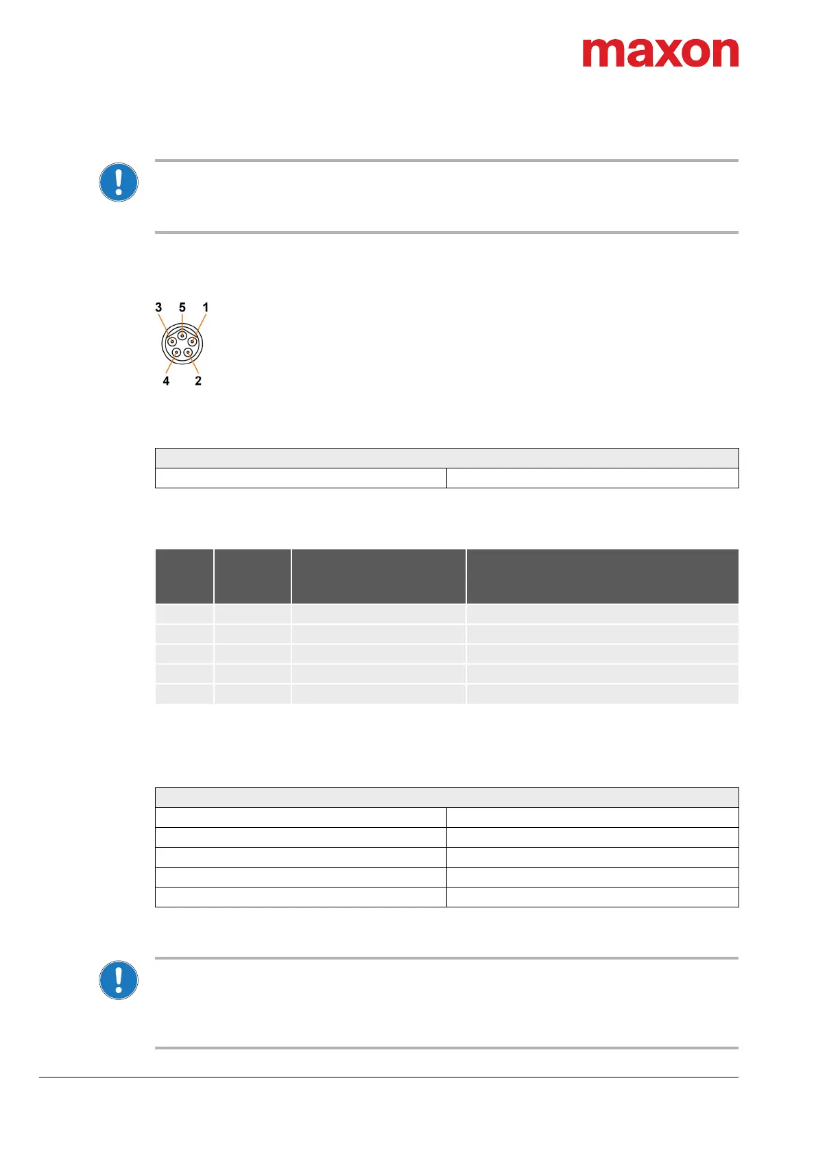
4.3.1 CAN IN (X1)
Figure 4-13 CAN IN connector X1
Table 4-10 CAN IN connector X1 – Specification
Table 4-11 CAN IN connector X1 – Pin assignment
For suitable prefab cable assemblies see Table 4-9 on page 4-27.
Table 4-12 CAN interface specification
CAN master settings and CAN bus termination
• Consider the CAN master’s maximal bit rate.
• The standard bit rate setting (factory setting) is 1 Mbit/s.
• Use 120
Ω
termination resistor at both ends of the CAN bus.
• For detailed information see separate document
«IDX Communication Guide».
CAN IN connector X1
Type M8, male, 5 poles, B-coded
X1
Head A
Prefab
cable
Signal Description
Pin Color
1 red CAN_V+ CAN external supply voltage
2 — CAN_SHLD CAN shield
3 white CAN_H CAN high bus line
4 blue CAN_L CAN low bus line
5 black CAN_GND CAN ground
CAN interface
Standard ISO 11898-2:2003
Max. bit rate 1Mbit/s
Max. number of CAN nodes 127 (via software setting)
Protocol CiA 301 version 4.2.0
Node-ID setting By software