4
the illumination of the Power Output Meters on Mc-
Intosh Power Amplifiers. A 3.5mm stereo mini phone
plug is used for connection to the Power Control, Trig-
ger and Passthru Outputs.
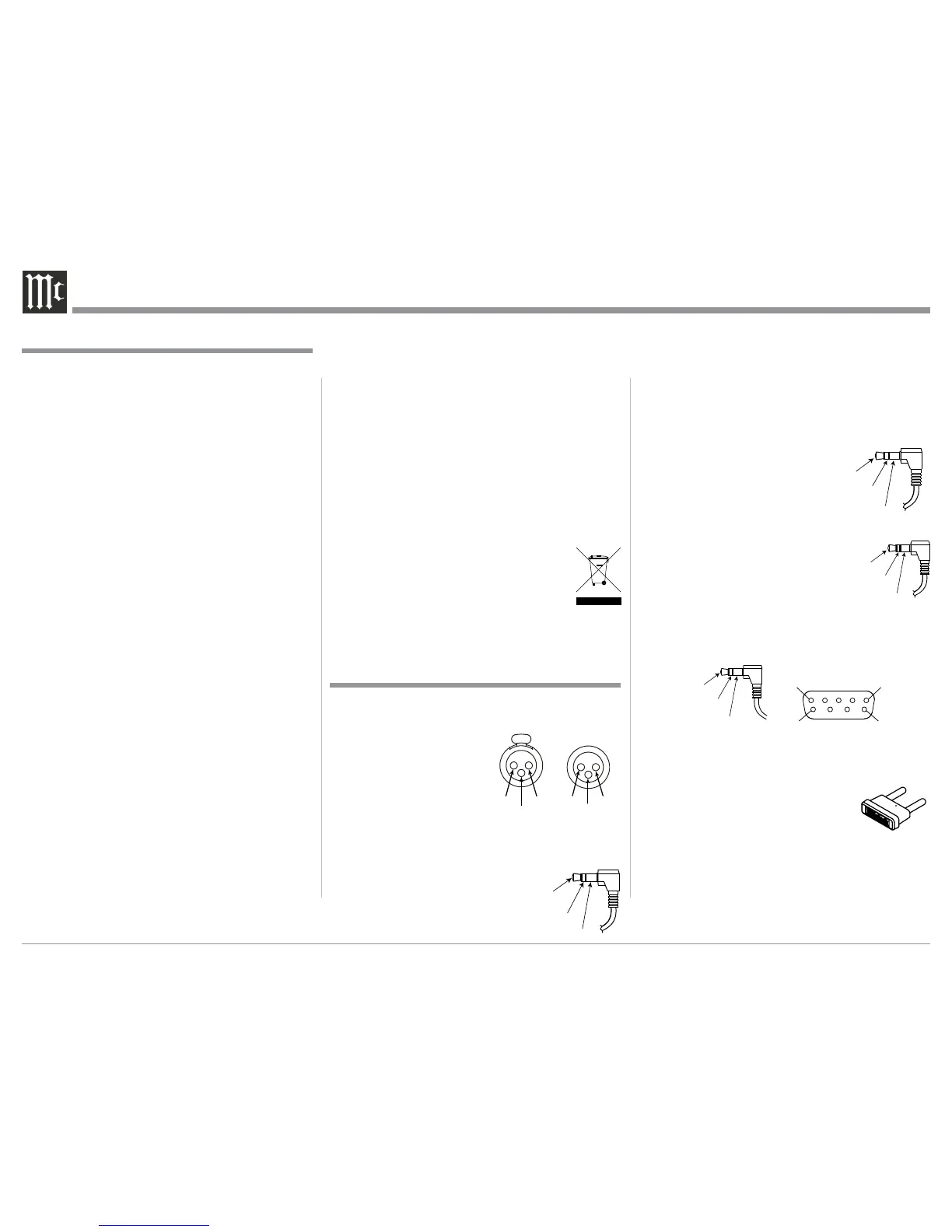
Data Port Connectors
The Data Out Ports send Remote
Control Signals to Source Compo-
nents. A 3.5mm stereo mini phone
plug is used for connection.
IR IN Port Connectors
The IR IN Port also uses a 3.5mm
stereo mini phone plug and allows the
connection of other brand IR Receiv-
ers to the MA8000.
RS232-C Data Port Cable
The RS232 Data Cable is a 3.5mm stereo mini phone
plug to a sub miniature DB 9 connector:
McIntosh Plug-In Jumper Connector
The MA8000 utilizes a phono style Plug-In Jumper to
connect the Preamplifier Output to the
Power Amplifier Input, one Jumper for
each channel.
Note: The Jumper Connector is available
from the McIntosh Parts Department:
McIntosh Jumper Connector Part No. 11808000
XLR Connectors
Below is the Pin configuration for the XLR Balanced
Input and Output Connectors on the MA8000. Refer
to the diagrams for connections:
PIN 1: Shield/Ground
PIN 2: + Output
PIN 3: - Output
Power Control and Trigger Connectors
The Power Control Trigger Output
Jacks send and Passthru Input Jack
receives Power On/Off Signals (+12
volt/0 volt) when connected to other
McIntosh Components. An addi-
tional connection is for controlling
1. For additional connection information, refer to the
owner’s manual(s) for any component(s) connected
to the MA8000.
2. Apply AC Power to the MA8000 and other McIn-
tosh Component(s) only after all the system compo-
nents are connected together. Failure to do so may
cause a malfunction of system operations as the
Microprocessor’s Circuitry inside the components
is active when AC Power is applied.
3. The MA8000 includes an Auto Off Power Save
Feature and the default setting is enabled. For
additional information including how to disable it,
refer to page 22.
4. When Power Amplifier Protection Circuitry of
the MA8000 has activated, the Front Panel Power
Guard LEDs are illuminated continuously and the
sound will be muted.
5. When the Power Transformer has overheated due
to improper ventilation and/or high ambient operat-
ing temperature, AC Power is removed from the
MA8000. Normal operation will resume when the
operating temperature is in a safe range again.
6. For the best performance and safety, it is important
to always match the impedance of the Loudspeaker
to the Power Amplifier connections. Refer to pages
11 thru 13.
Note: The impedance of a Loudspeaker actually var-
ies as the Loudspeaker reproduces different
frequencies. As a result, the nominal impedance
rating of the Loudspeaker (usually measured at
a midrange frequency) might not always agree
with the impedance of the Loudspeaker at low
frequencies where the greatest amount of power
is required. Contact the Loudspeaker Manufac-
turer for additional information about the actual
impedance of the Loudspeaker before connecting
it to the McIntosh MA8000.
7. The MA8000 Remote Control is capable of operat-
ing other components. For additional information
go to www.mcintoshlabs.com.
8. The IR Input, with a 1/8inch mini phone jack, is
configured for non-McIntosh IR sensors such as
a Xantech Model HL85BK Kit. Use a Connection
Block such as a Xantech Model ZC21 when two
or more IR sensors need to be connected to the
MA8000. The signal from a connected External
IR Sensor will have priority over the signal from
the Front Panel IR Sensor.
9. When discarding the unit, comply with local rules
or regulations. Batteries should never be
thrown away or incinerated but disposed
of in accordance with the local regula-
tions concerning battery disposal.
10. For additional information on the
MA8000 and other McIntosh Products please visit
the McIntosh Web Site at www.mcintoshlabs.com.
Connector and Cable Information
Data
Signal
N/C
Data
Ground
General Information
Power
Control
Meter
Illumination
Control
Ground
Main, Trig 1&2
and Pass-Thru
IR Data
Control
Ground
N/C
General Information, Connector and Cable Information
PIN 1
PIN 6
PIN 5
PIN 9
Data In
(DB9-pin2)
Ground
(DB9-pin5)
Data Out
(DB9-pin3)
DB9
(male connector)
PIN 2 PIN 1
PIN 3
PIN 1
PIN 2
PIN 3
 Loading...