29
12.2 INSERT
To verify the final height of the insert, prior to implanting the
definitive tibial insert, the trial insert can be positioned on
the final baseplate.
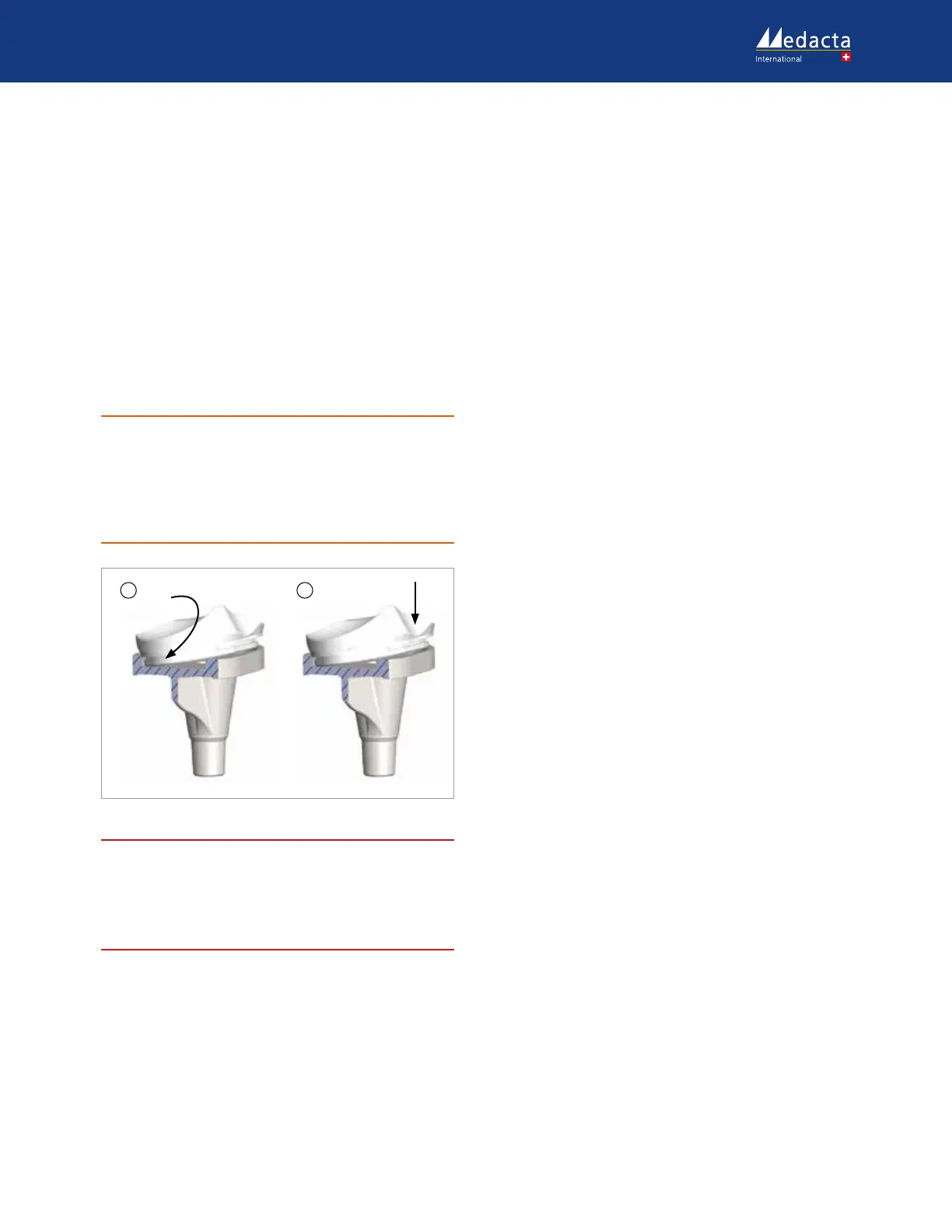
Place the insert on the tibial baseplate according to the
following steps:
1. Make sure that the metallic upper surface of the tibial
baseplate is perfectly clean and that no small debris can
get interposed between tray and insert during assembly.
2. Engage the posterior lips of the insert in the posterior
part of the tibial baseplate.(A)
3. Clip the anterior part of the insert, by exerting pressure
on it manually.(B)
CAUTION
Once the posterior lips of the insert are fully engaged into
the posterior part of the tibial baseplate, apply downward
pressure to clip it firmly in position. If difficultly is
experienced whilst trying to clip the insert in place, remove
and reposition it. A ‘click’ will be heard or felt when the
insert is correctly connected.
BA
66.
WARNING
When using a GMK Sphere Flex insert, it can be further
secured through an optional screw packaged together with
it. If the screw option is chosen, the torque limiter
screwdriver 3.5 N·m must be used to guarantee that the
optimal locking of the screw is achieved.
12.3 FEMORAL IMPLANT
Attach the femoral impactor to the slide hammer. Open the
femoral impactor jaw and attach it to the femoral
component using the two lateral slots. Lock together by
turning the handle firmly.
The bone cement must be prepared according to the
cement manufacturer’s instructions. Once the cement
reaches the right viscosity, it must be applied to the internal
surface of the femoral implant into the corresponding
cement pockets. The resected bone surface should be
thoroughly cleaned by pulse lavage and the intramedullary
canal closed by cancellous bone. Position the femoral
implant using the previously drilled peg holes for correct
alignment and finish by impacting with the dedicated
femoral impactor. Once the femoral implant has been fully
inserted with the dedicated impactor, the extruded cement
is cleared from the femur, ensuring that no cement remains
on the articular surface, on the intercondylar notch and in
the joint, in order to avoid excessive UHMWPE wear.
12.4 PATELLA
Assemble the spike jaw and the pressurizing jaw on the
patellar clamp. The pressurizing jaw has the blue side
specifically designed for the resurfacing patella. The bone
cement must be prepared according to the cement
manufacturer’s instructions. Once the cement reaches the
right viscosity, it should be applied to the internal surface
of the patellar implant. Lock the patella, by firmly screwing
the thumbwheel switch of the patellar clamp. Hold the
implant in the final position and clear the extruded cement
from the patella, ensuring that no cement remains on the
articular surface.