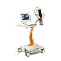
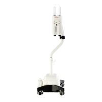
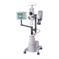
Mark V ProVis Injection System
16 - 34
Line Voltage Conversion (continued)
3. Locate the power transformer. When changing the configuration,
refer to the following table for wiring guidelines. Do not change the
wires on the X side.
Line Neutral Hot Jumper
Voltage (blue) (brown) (white/brown)
100 VAC H2 and H6 H1 and H5 n/a
110 VAC H3 and H7 H1 and H5 n/a
125 VAC H4 and H8 H1 and H5 n/a
200 VAC H6 (only) H1 (only) H2 to H5
230 VAC H7 (only) H1 (only) H3 to H5
250 VAC H8 (only) H1 (only) H4 to H5
4. Replace the bottom cover of the Control Unit.
5. Mate the harness connectors together.
6. (Pedestal Systems only) Replace the RF shield and secure with
the twelve (12) screws previously removed.
7. (Pedestal Systems only): Position the electronic console in the
pedestal assembly and secure with the four mounting screws.
8. Connect the injector head to the rear connector panel.
9. (Pedestal Systems only): Re-establish all cable connections at the
rear connector panel, then install and secure the rear access pan
-
els with the four screws previously removed.
10. (Rackmount Systems only): Tilt the Front Panel upward, then
secure by tightening the two captive screws.
11. Apply power to the injector, then confirm proper unit operation.


 To Next Page