Do you have a question about the Megaplot XMD Series and is the answer not in the manual?
Details the materials XMD CNC routers can process and their suitability for 2D/3D projects.
Introduces MegaCut for 2D and MegaCut3D for 3D projects, highlighting their features.
Presents specifications for XMD32, XMD46, and XMD48 models, including working area and power.
Lists the standard components and software provided with the CNC router.
Describes the functionality of the optional wired remote control for machine operation.
Explains the purpose and components of the optional tool cooling system for metalworking.
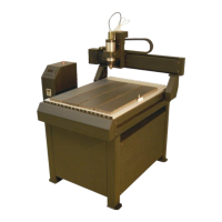
Identifies key components of the CNC router, including controller, spindle, and emergency switch.
Details the requirements for connecting the router to a power source, emphasizing grounding.
Explains the information shown on the controller's LCD screen and the inverter display.
Details the remote control's display and the function of each button for machine operation.
Provides detailed explanations for the functions of various buttons on the wired remote control.
Explains the 'STOP' button functionality on the wired remote control for halting the cutting process.
Explains the difference between the machine's fixed home position and the user-defined project starting position.
Details supported file formats for 2D projects (PLT, DXF, NC) and best practices for vector drawings.
Specifies requirements for DXF files, including layer usage, block avoidance, and text conversion.
Explains how to correctly mark locations for drilling holes in 2D drawings.
Addresses the issue of double engraving with single-line fonts and how to prevent it.
Details the file formats (RAW, DXF 3D, BMP) supported for importing 3D models.
Guides on positioning 3D models in the coordinate system for optimal tooling.
Explains the impact of Z-axis position and recommended model dimensions and PC specs for 3D work.
Details how grayscale BMP files are used for depth calculation and requirements for smooth surfaces.
Describes the G-code file format and its required .nc extension for MegaCut.
Lists and explains the G-code commands that the MegaCut software recognizes.
Provides examples of G-code syntax, including full/short terminology and handling of conflicting commands.
Explains how to use both absolute and incremental addressing modes within a single G-code file.
Details MegaCut 2D's capabilities, including precise tooling, multi-layer support, and G-code compatibility.
Outlines the sequential steps required to safely start up the CNC machine and MegaCut 2D software.
Explains how to set the language for the MegaCut 2D software and its default behavior.
Instructions on modifying the software shortcut to force a specific language version for MegaCut.
Steps to enable a touch-screen friendly interface by modifying the software shortcut.
Overview of the MegaCut 2D main window, including menus, shortcuts, and status bar.
Details the 'Info' pop-up window options for viewing project dimensions, time, scale, and tool diameter.
Guides on opening drawings, checking dimensions, and troubleshooting size discrepancies.
Emphasizes the importance of simulation before cutting to ensure the correct tooling sequence.
Explains when simulation is unavailable and how to set cutting direction and sequence in Configuration.
Details how to enter the Configuration window to adjust various machine and software parameters.
Configures automatic processes like node connection and overlapping shape removal during import.
Sets the project type to Single-layer or Multi-layer, affecting depth settings.
Covers settings like skipping the frame, scaling drawings, and G-code coordinate interpretation.
Defines the cutting sequence for shapes, prioritizing insides, outsides, or original order.
Sets the tooling direction for external and internal objects to ensure cut quality.
Configures essential tooling parameters like tool diameter, speeds, and spindle rotations.
Defines tool diameter and material thickness, crucial for accurate path calculation and depth.
Configures milling depth, spiral slip for hard materials, cutting speed, and spindle rotations.
Explains curve smoothing for better quality and polishing for improved surface finish.
Configures drilling speeds (up/down) and drill slip for precise hole creation.
Configures settings for the tool length measurement plate, including thickness and position.
Sets up IP address for plotters and enables LAN (Ethernet) connection for network communication.
Sets measurement units and defines the spindle's post-cut movement (return to zero or go to XY).
Explains the necessity of tool length measurement and the methods for performing it.
Details requirements for accurate automatic tool length measurement, including plate and pad preparation.
Step-by-step guide for the automatic tool length measurement process, including verification.
Alternative method for measuring tool length using manual control and specific input values.
Guides on preparing and initiating the cutting process after setting parameters and running simulation.
Explains how to pause, resume, or restart the cutting process from any point.
Introduces multi-layer drawings, where different colors represent layers with specific cutting depths.
Guides on preparing multi-layer drawings by color-coding layers for PLT and DXF files.
Instructs on setting the project type to 'Multi-layer' in the Import tab for proper depth handling.
How to adjust depth and enable/disable individual layers within the Layers window.
Explains how to deactivate entire layers or specific objects, and how to re-activate them.
Describes how initial depths are calculated for PLT files based on pen width and depth multiplier.
Explains how initial depths are determined for DXF files from the CNC tab settings.
Details how to perform the lining operation to clear the inside of closed shapes.
Explains how parameters like 'Cut the negative' and 'Skip the frame' affect the lining process.
Discusses how spiral slip setting applies to lining and how lining combines with multi-layer drawings.
Describes the manual control window's capabilities, including axis movement and spindle rotation control.
Ensures spindle cooling is active before rotation and explains the homing procedure.
Covers setting the project's starting position and moving the machine by declared distances.
Explains the function of homing to return the machine to its original position using proximity sensors.
Provides tips for ensuring the homing process is accurate, focusing on sensor and screw cover cleanliness.
Details how to set and save multiple project starting locations for easy recall.
Explains the 'Move' window for precise axis movements to machine or project coordinates.
Outlines the initial step of connecting the controller to the PC via USB before Ethernet setup.
Steps to enable Ethernet communication, including modifying shortcuts and setting IP addresses.
Details creating a 'kalibracja.txt' file with axis calibration values for the MegaCut folder.
Provides the formula and acceptable range for calculating axis calibration adjustment values.
Explains MegaCut3D's use for cutting 3D models from various formats and external preparation.
Details the start-up sequence for MegaCut3D and the mandatory software activation process.
Guides on obtaining and entering an activation code to unlock full MegaCut3D functionality.
Instructions for changing the MegaCut3D software language by modifying its shortcut.
Steps to modify the shortcut to force a specific language for the MegaCut3D application.
How to enable a touch-screen friendly interface for MegaCut3D by adjusting the software shortcut.
Details the MegaCut3D window, including model/tool path previews, tool library, and operations list.
Explains the information displayed on the bottom bar, including progress and project name.
Provides a high-level overview of the standard steps involved in a 3D tooling process.
Step-by-step guide for achieving best results in 3D tooling, from machine setup to output file generation.
Describes the different ways to load a 3D model into the MegaCut3D software.
Emphasizes checking model dimensions and Z-axis position against material before starting cuts.
Details how grayscale BMP files are converted into 3D models, including height value settings.
Explains how to scale BMP files for length and height to match desired model dimensions.
Configures material dimensions, source (e.g., from file), and shell settings.
Guides on controlling the model's cutting height within the material using height and pad thickness.
Recommends leaving a 1mm layer on top for optimal material usage, especially with layering.
Explains how adjusting BMP black and white values affects model positioning and height.
Describes the tools library, sorted by diameter, and how to manage tools.
Explains the different tool types (flat, ball, conical) and their primary applications in tooling.
Introduces the concept of defining multiple operations, starting with roughing and finishing.
Details the six types of operations: Roughing, Layering, Surfacing, Lining, Lining from file, Mixed.
Explains roughing for excess material removal and lining for parallel line finishing.
Describes layer, surface, and mixed operations, detailing their specific movement and application.
Configures layer width, depth, and soft start for roughing operations.
Sets speed, rotations, and Z-axis limits for the roughing operation.
Covers specific parameters for layer, mixed, and lining operations like connectivity and angles.
Explains how to generate output files based on defined operations and the time factor.
Describes the output file generation process, including status bar information and file parameters.
Explains the necessity of tool length measurement and the recommended method (table level).
Illustrates different scenarios for placing the material and measuring plate for tool length.
Highlights the importance of setting correct pad thickness in Configuration for accurate measurement.
Reiterates prerequisites for automatic measurement, including plate cleanliness and spindle reach.
Step-by-step instructions for performing automatic tool length measurement and verifying its success.
Detailed steps for semi-automatic tool length measurement using the Manual Control interface.
Important safety notes and precautions for semi-automatic measurement to prevent damage or injury.
Ensures spindle cooling is active and spindle is positioned correctly before starting a cut.
Guides on selecting output files, starting the cut, and using STOP/CONTINUE for process control.
Explains how to restart a cut from a specific point after an interruption like a power outage.
Reiterates key functions of Manual Control, including axis movement and spindle cooling.
Displays both the standard and touch-friendly versions of the Manual Control window.
Reiterates the importance of homing the machine after movement blockages or tool stumbles.
Details saving and managing multiple project starting locations for efficient workflow.
Explains how to use the 'Move' window to precisely position the machine axes.
Sets measurement units (mm/inches) and resolution (points/mm) for output file calculation.
Configures plotter IP, tool length measurement plate position, and enables LAN connection.
Specifies requirements for router placement, power connection, and compatible PC operating systems.
Advises turning off power saving modes and notes limitations on drawing/model size and concurrent software use.
Details the four fundamental lining patterns: Vertical, Horizontal, Forward Slash, and Back Slash.
Explains how enabling 'All elements of a shape' prioritizes cutting internal lines before outlines.
Describes cutting sequence when 'All elements of a shape' is disabled, prioritizing all lines first.
Instructions on deleting overlapping lines during drawing import in MegaCut.
Explains how the 'Connect the nodes' feature can affect overlapping line deletion.
Recommends regular cleaning and greasing of ball screws and linear guides for longevity.
Advises keeping proximity sensors clear and cleaning chips with compressed air, avoiding vacuum.
Ensures proper operation of the water cooling system and advises using suitable tools to avoid spindle overload.
| Brand | Megaplot |
|---|---|
| Model | XMD Series |
| Category | Power Tool |
| Language | English |