M
AVTMTTR330 Rev 3 March 2010
12
2. Connect the H and X test cables to the respective H and X receptacles of the
TTR330. Make sure that the connectors are securely fastened (using
clockwise rotation) to the receptacles.
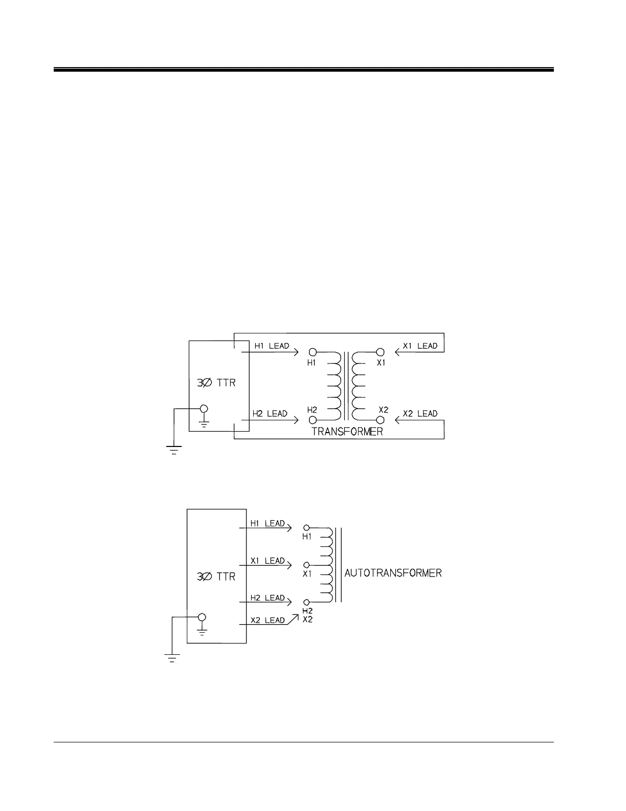
3. Connect the heavy-duty clamps marked H1 and H2 of the test lead to the
corresponding (high-voltage winding) terminals of the transformer under
test. Figures 4-1 and 4-2 show test setups for single-phase transformers.
Figures 4-3 and 4-4 show test setups for regulators.
4. Connect the heavy-duty clamps marked X1 and X2 of the test lead to the
corresponding (low-voltage winding) terminals of the transformer under test.
Figures 4-1 and 4-2 show test setups for single-phase transformers. Figures
4-3 and 4-4 show test setups for regulators.
5. On/OFF Switch. It is only after all of the above connections are safely made
and all safety precautions of sections 2 and 3 are satisfied, should the
On/OFF switch be turned to the ON position.
Figure 4-1. Setup for Testing Single-Phase Transformer
Figure 4-2. Setup for Testing Single-Phase Autotransformer
To test windings other than H1 – H2 and X1 – X2, ensure that the heavy-duty
clamp marked H1 is connected to the lower numbered terminal and H2 to the