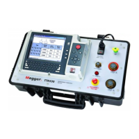
Getting to Know the TTR330
AVTMTTR330 Rev 3 March 2010
3
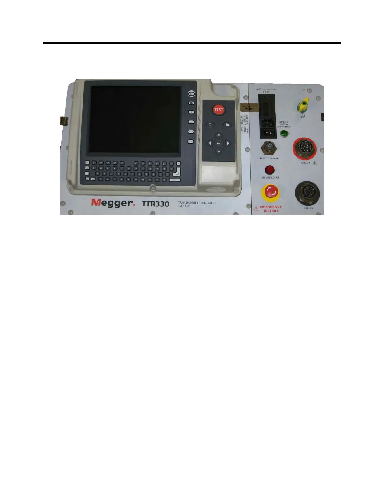
Top Panel Controls
Figure 1-1 Top Panel Controls
1. Power input receptacle, ON/OFF switch, and fuse holder. ON/OFF power
switch and input power receptacle provides power to the test set.
2. Emergency OFF switch. This red push button interrupts testing. When
pressed, the switch is locked in off position. To reset the switch, twist the
button in the direction indicated by the arrows.
3. Voltage ON light. Red indicator lamp indicates when lit that test voltage is
being supplied to the Unit Under Test (UUT).
4. Remote Trigger receptacle. Plug receptacle for connecting Remote Trigger
cable for testing transformers with Load-Tap-Changers.
5. H – Cable receptacle. Plug receptacle for connecting test leads to the high-
voltage (H) winding of a transformer
6. X – Cable receptacle. Plug receptacle for connecting test leads to the low-
voltage (X) winding of a transformer.
7. Ground lug. Wing-nut terminal allows connection of test set to Station Earth
ground.