M
AVTMTTR330 Rev 3 March 2010
14
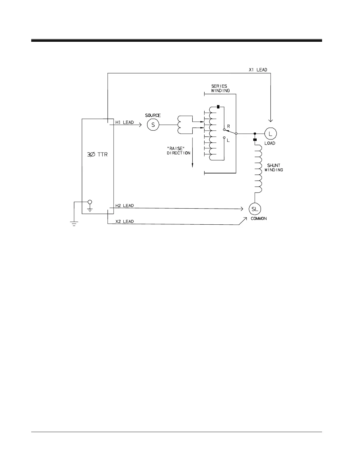
Figure 4-4. Setup for Testing Single-Phase, Type B (Inverted Design) Step Voltage Regulator
Three-Phase, Two-Winding Transformers
Perform the following setup procedure for three-phase, two-winding
transformers:
1. With the ON/OFF Switch in the OFF position, make the circuit
connections as described in Section 3.
2. Connect the H and X test cables to the respective H and X receptacles of the
TTR330. Make sure that the connectors are securely fastened (using
clockwise rotation) to the receptacles.
3. Connect the heavy-duty clamps marked H0, H1, H2, and H3 of the test lead
to the corresponding (high-voltage winding) terminals of the transformer
under test. Refer to Table 4-2 for test lead markings. With delta connected
windings, H0 is not used. With wye connected windings, a neutral
connection for H0 is normally available.
4. Connect the heavy-duty clamps marked X0, X1, X2, and X3 of the test lead
to the corresponding (low-voltage winding) terminals of the transformer
under test. Refer to Table 4-2 for test lead markings. With delta connected
windings, X0 is not used. With wye connected windings, a neutral connection
for X0 is normally available.