Connecting to the Transformer
AVTMTTR330 Rev 3 March 2010
17
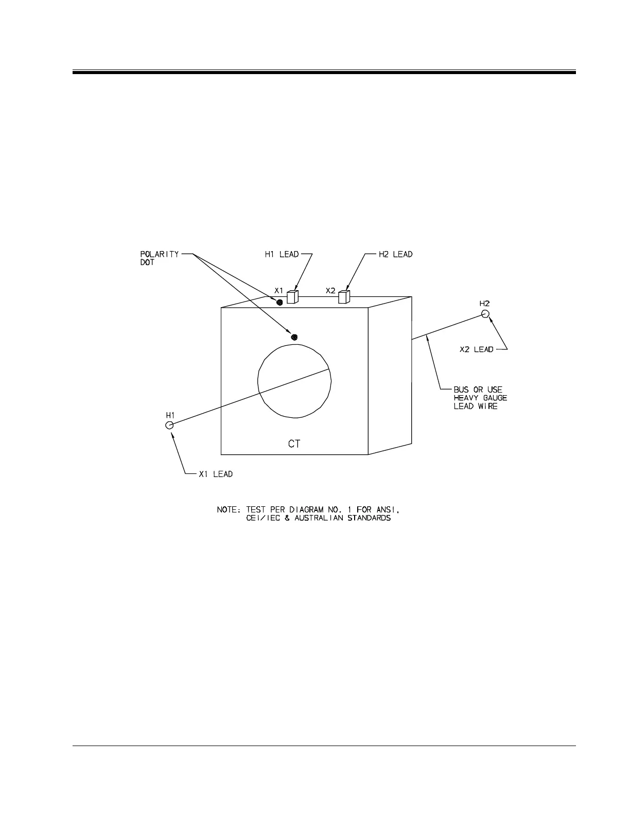
3. As shown in Figure 4-5, connect the heavy-duty clamps marked H1 and H2
of the test lead to the respective X1 and X2 terminals of the CT. Note that
the H and X leads are connected in reverse as compared to the Single and
Three phase Transformer testing described in the previous sections.
4. As shown in Figure 4-5, connect the heavy-duty clamps marked X1 and X2
of the test lead to the respective H1 and H2 terminals of the CT. Ensure
correct polarity. Note that the H and X leads are connected in reverse as
compared to the Single and Three phase Transformer testing described in the
previous sections.
Figure 4-5. Setup for Testing Unmounted Current Transformer