Connecting to the Transformer
AVTMTTR330 Rev 3 March 2010
13
higher numbered terminal of the high-voltage winding. Similarly, X1 and X2
should be connected to the low-voltage winding.
Test lead markings for the ANSI, CEI/IEC, and Australian standards are as
shown in Table 4-1.
Table 4-1. Test Lead Markings for Single-Phase Transformers
Test Lead Marking Transformer Heavy-Duty
Clamp
Test Lead
ANSI CEI/IEC Australian Terminal Voltage Boot Color Color Band
H1 1 U A
2
High Red Red
H2 1 V A
1
High Red Yellow
X1 2 U a
2
Low Black Red
X2 2 V a
1
Low Black Yellow
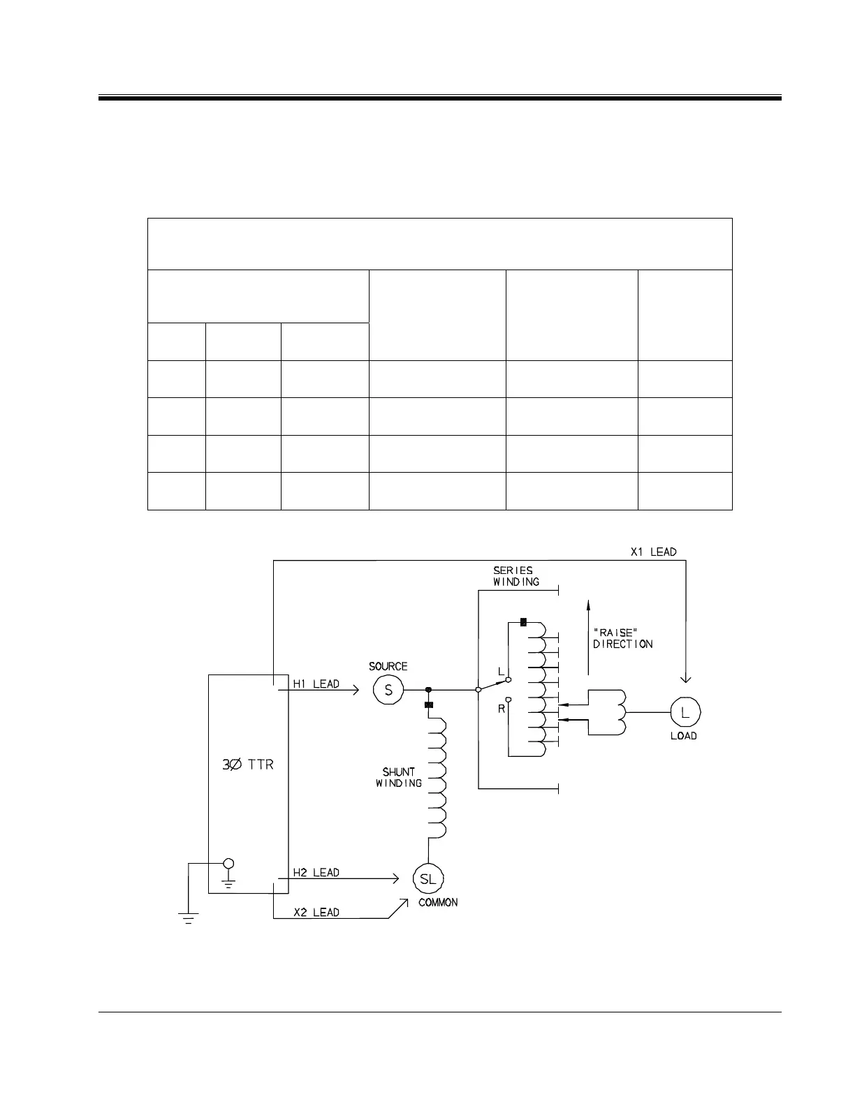
Figure 4-3. Setup for Testing Single-Phase, Type A (Straight Design) Step Voltage Regulator