Connecting to the Transformer
AVTMTTR330 Rev 3 March 2010
15
5. On/OFF Switch. It is only after all of the above connections are safely
made and all safety precautions of sections 2 and 3 are satisfied, should the
On/OFF switch be turned to the ON position.
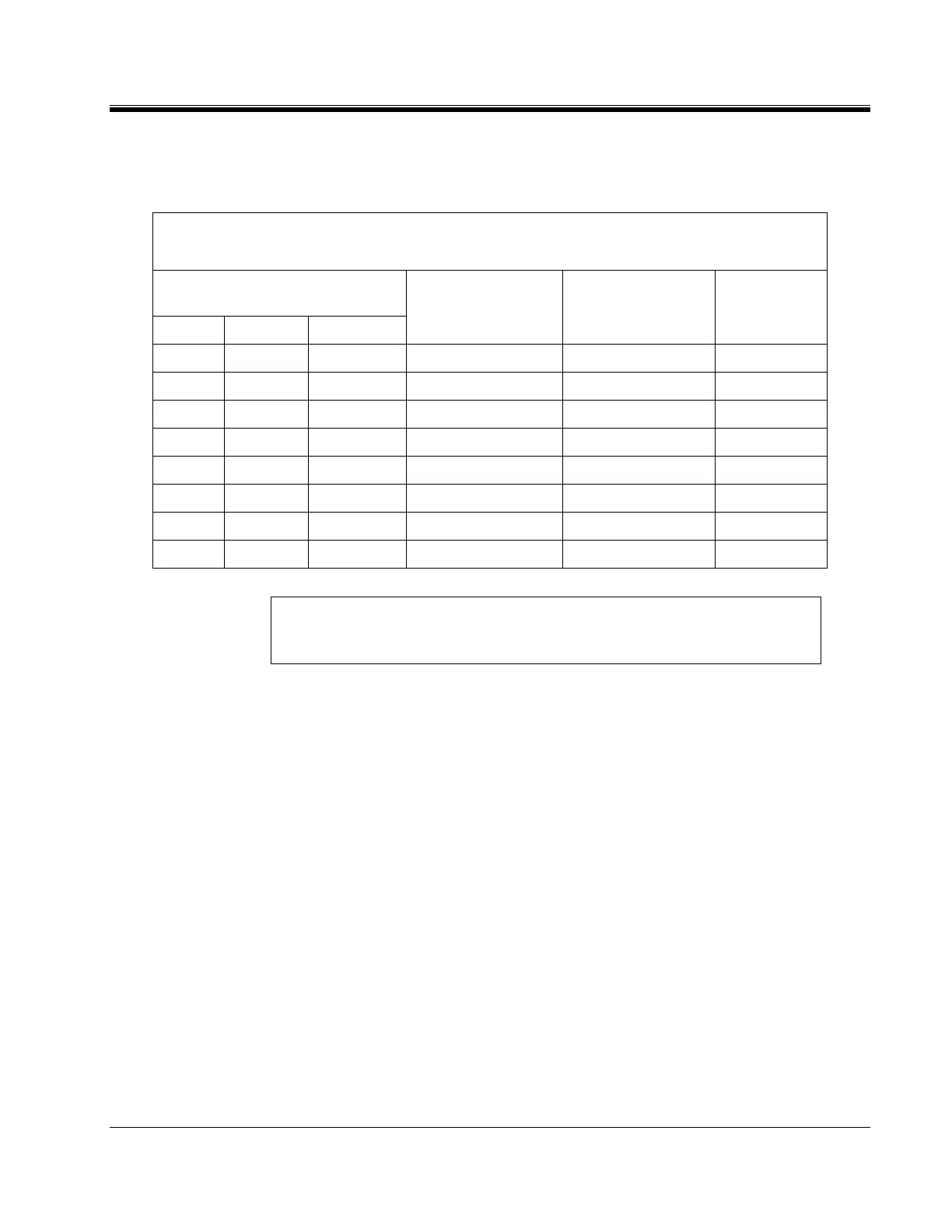
Table 4-2. Test Lead Markings for Three-Phase Transformers
Test Lead Marking Transformer Heavy-Duty
Clamp
Test Lead
ANSI
CEI/IEC Australian Terminal Voltage Boot Color Color Band
H0 1N N Neutral Red White
H1 1U A
2
/A
4
High Red Red
H2 1V B
2
/B
4
High Red Yellow
H3 1W C
2
/C
4
High Red Blue
X0 2N N Neutral Black White
X1 2U a
1
/a
2
/a
4
Low Black Red
X2 2V b
1
/b
2
/b
4
Low Black Yellow
X3 2W c
1
/c
2
/c
4
Low Black Blue
Note: According to Australian standard, wye and delta transformer winding
connections have a numerical suffix of 1 and 2. The zigzag transformers
have a numerical suffix of 4.
Three-Phase, Three-Winding Transformers
This type of transformers has primary, secondary, and tertiary windings. Primary
and secondary windings are tested as a regular three-phase, two-winding
transformer. To test tertiary winding, perform the following setup procedure:
1. With the ON/OFF Switch in the OFF position, make the circuit
connections as described in Section 3.
2. Connect the H and X test cables to the respective H and X receptacles of the
TTR330. Make sure that the connectors are securely fastened (using
clockwise rotation) to the receptacles.
3. Connect the heavy-duty clamps marked H0, H1, H2, and H3 of the test lead
to the corresponding terminals of the transformer under test. Refer to Table
4-2 for test lead markings. With delta connected windings, H0 is not used.
With wye connected windings, a neutral connection for H0 is normally
available
4. Connect the heavy-duty clamps marked X0, X1, X2 , and X3 of the test lead
to the corresponding tertiary (low-voltage winding) terminals (Y0, Y1, Y2,