257
5.5 520W/100Ω 120
7.5 780W/75Ω 200
11 1040W/50Ω 200
15 1560W/40Ω 200
18.5 4800W/32Ω 200
22 4800W/27.2Ω 200
30 6000W/20Ω 150
37 9600W/16Ω 120
45 9600W/13.6Ω 200
55 6000W/20Ω*2 160
75 9600W/13.6Ω*2 120
Note
1. For the drive with internal brake units, the user only needs to configure external braking resistor when the
dynamic braking is required. The recommended resistor specification for 22kW drive is 3kW, 20Ω.
2. Please refer to Attached Table 2-2 when configuring the braking unit of 90kW or above.
4. Wring and use
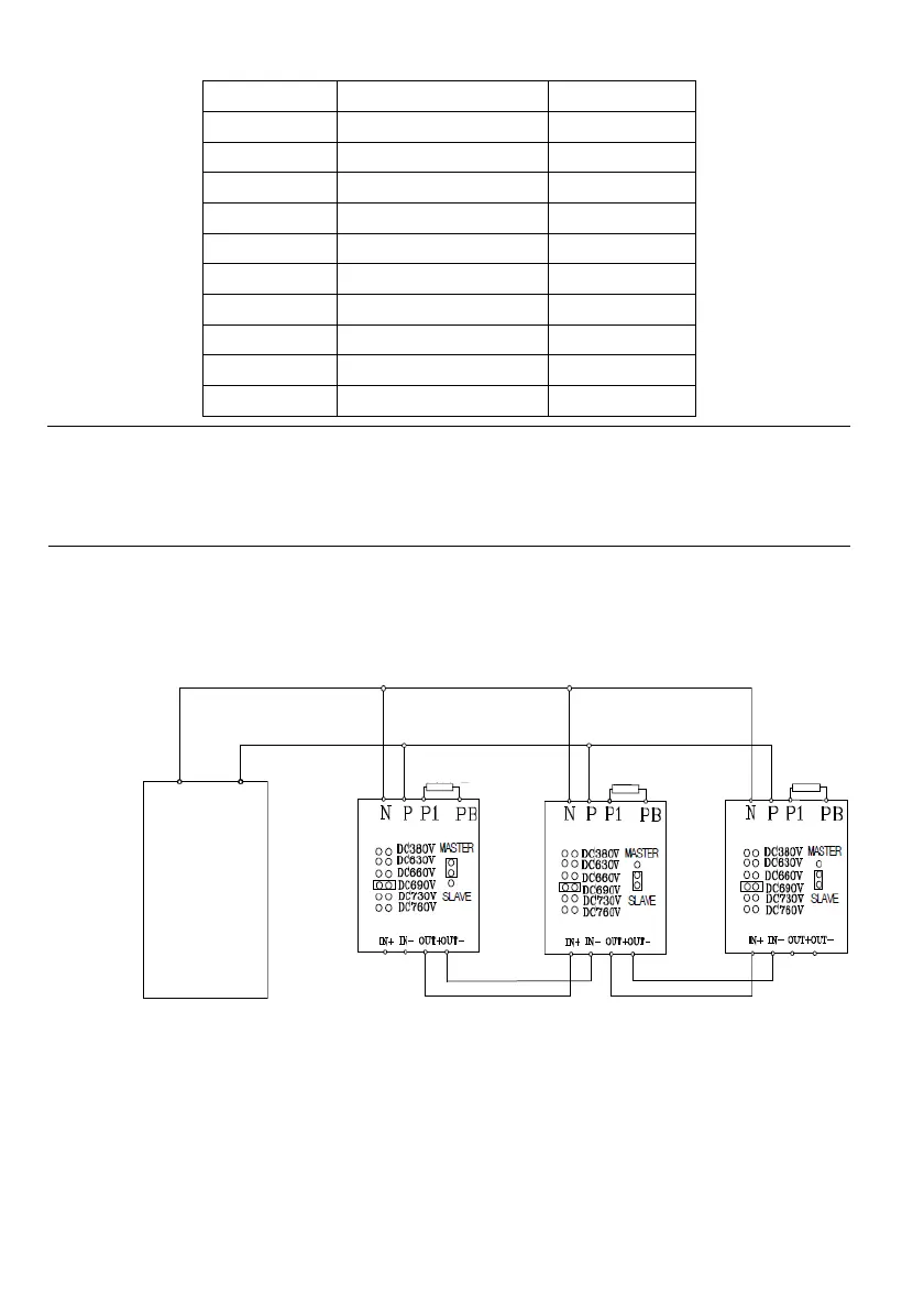
1) Wiring of the built-in brake units of the drive
Please connect the brake resistor to the P/B1 and B2 terminals of drive main circuit.
2) External wiring diagram of external brake unit DBU-4030/4045
Attached Fig.2-2 Connection diagram of the drive and brake unit
3) Diagram for external wiring of DBU-4220/4300
Drive
+DC -DC
Brake Resisto
Brake Resisto
Brake Resisto
 Loading...