4 Description of the device
13
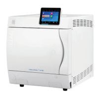
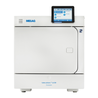
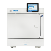
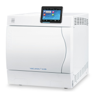
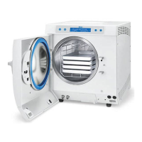
Views of the device
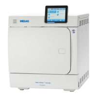
Fig.1: View from front
1 CF card slot
2 Colour touch display
3 LED status bar
4 Energy-saving key
5 Door (swings open to the left)
6 Opening for door opening in an
emergency*
)
7 Opening for emergency activation
of the vacuum pump
8 Power switch (covered,
accessible from the side)
9 Ethernet connection
10 Motor protection switch reset
button
11 Overheat control reset button
12 Allen key 5mm to open the door
in an emergency
13 Front device foot (adjustable)
14 Manometer for pressure display
on the double-jacket steam
generator
*
)
behind cover
23
24
25
22
18
16
17
21
15
20
19
27 26
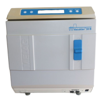
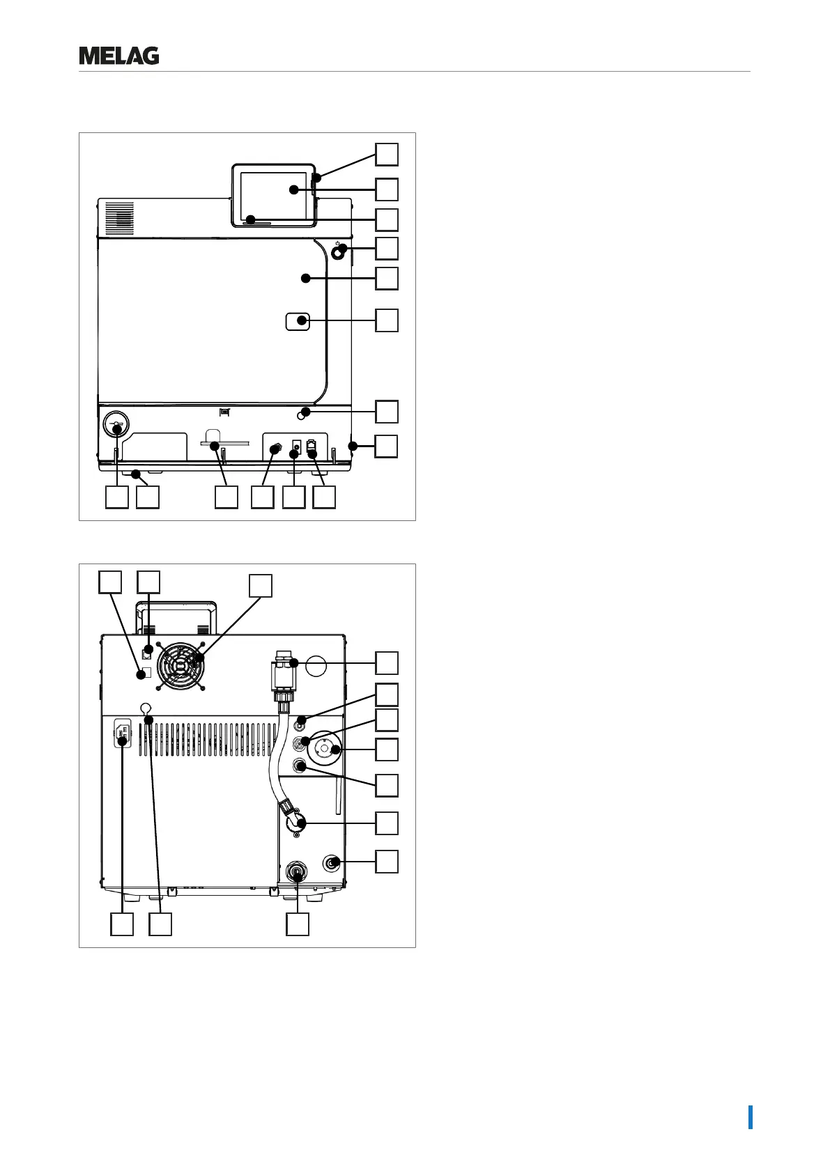
Fig.2: View from rear
15 Ethernet connection
16 Ethernet connection, optional
(upgradeable)
17 Fan
18 Safety combination in accordance
with EN 1717
19 Cavitation protection nozzle and
valve
20 Spring safety valve chamber
21 Sterile filter
22 Spring safety valve double jacket
23 Cooling water inflow valve (3/4”
external thread)
24 Feed water inflow for external
water storage container or water
treatment unit (e.g. MELAdem)
25 Cooling water outflow valve (3/4”
external thread)
26 Optional connection of a Flex
display
27 Power cable connection