Rev 2.2 94Mellanox Technologies
C.2 SFP28 Pin Description
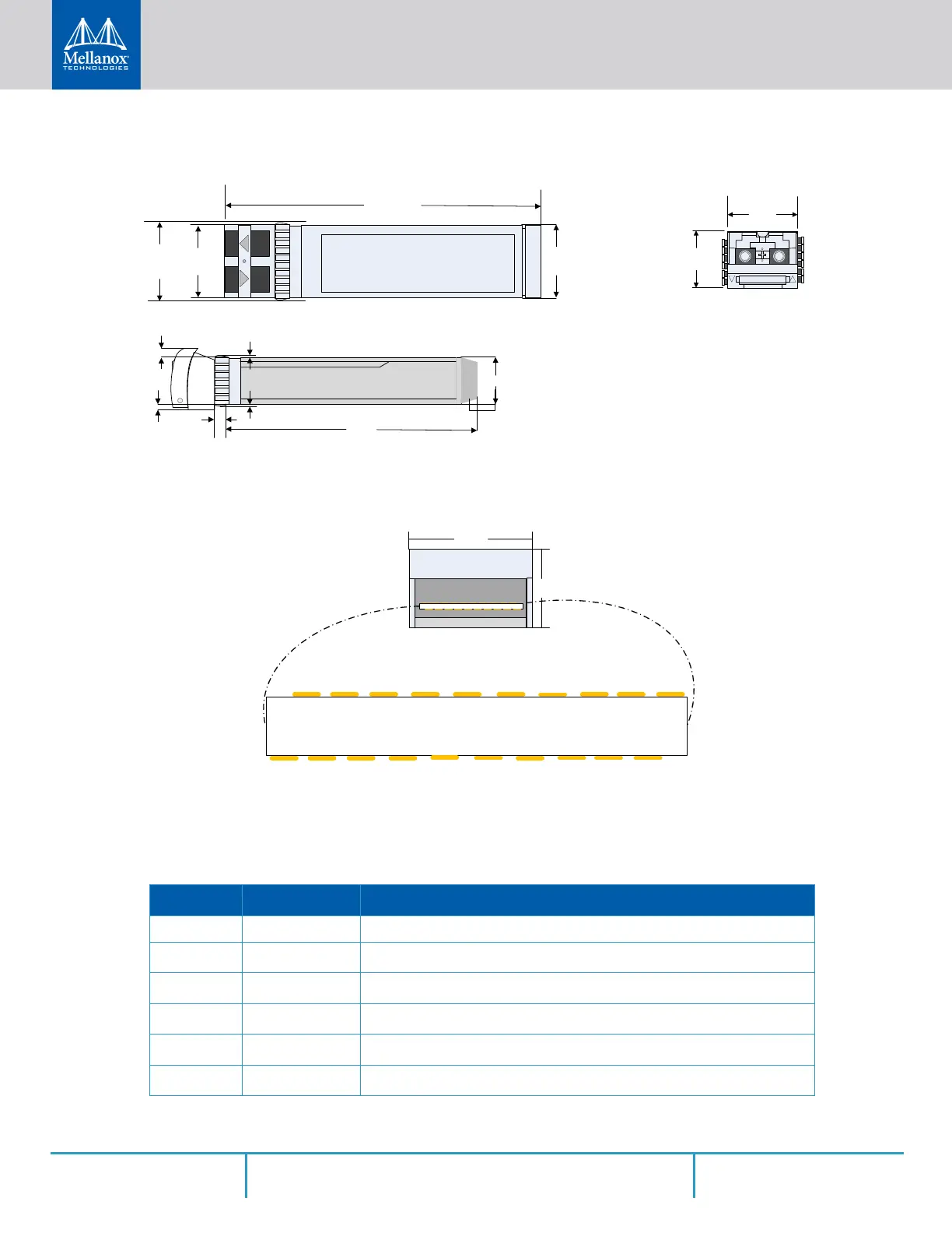
Figure 86: Rear View of Module With Pin Placement
Table 33 - SFP Pin Description
Pin Symbol Name Description
1 VeeT Module Transmitter Ground
2 TX_Fault
Module Transmitter Fault
a
3 TX_Disable
Transmitter Disable. Turns off transmitter laser output
b
4 SDA
2-wire Serial Interface Data Line
c
5 SCL
2-wire Serial Interface Clock Line
d
6 MOD_ABS
Module Absent. Grounded within the module
d
Mellanox Technologies
MTSFPP-SR Module
14.80
13.60
56.50
13.70
1.80
1.55
44.95
8.50
2.55
0.50
0.60
13.70
8.50
Top
VeeT
VeeT
VeeT
TX_Fault
TX_Disable
SDA
SCL
MOD_ABS
RS0
RX_LOS
RS1
VeeR
VeeR
VeeR
VccT
VccR
TD+
TD-
RD-
RD+
1
2
3
4
5
6
7
8
9
1
2
3
4
5
6
7
8
9
0
1
1
1
1
1
1
1
1
1
2
10
 Loading...