CHARGING & STARTING SYSTEM
Page 2B-14 90-883728 JULY 2001
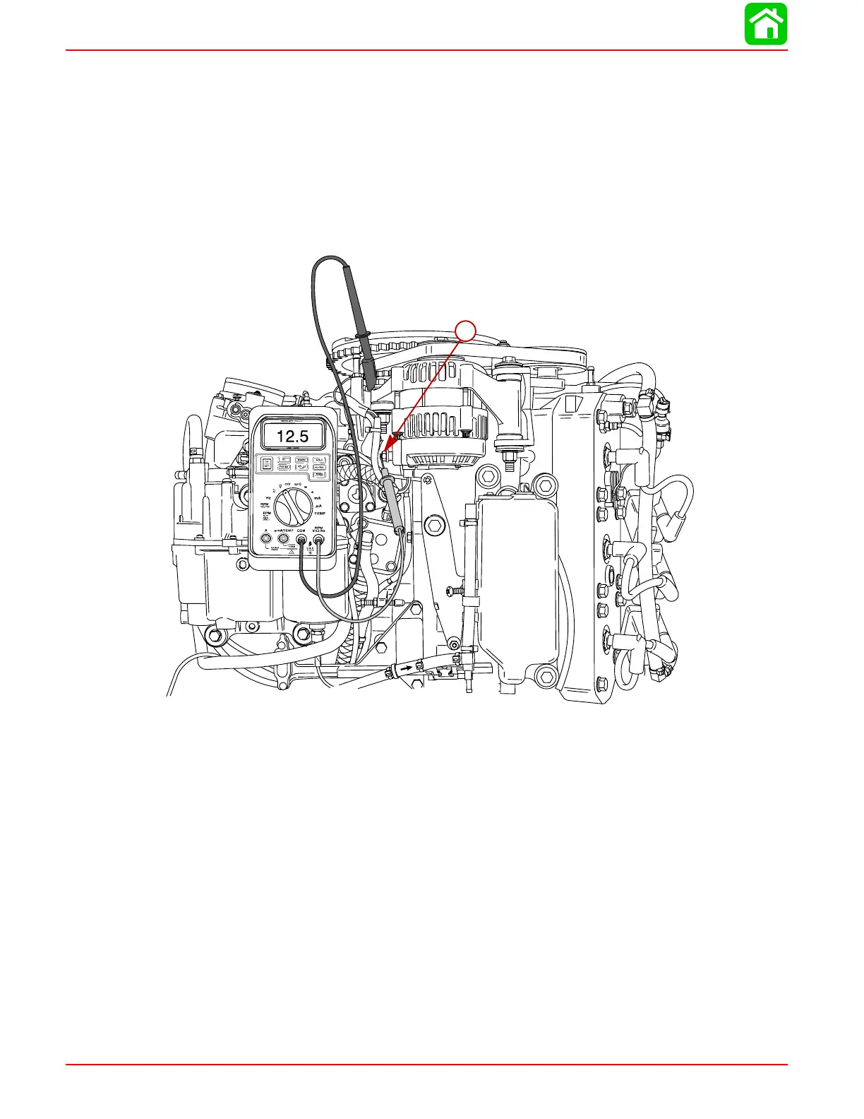
Alternator System Circuitry Test
Using a 0-20 volt DC voltmeter, perform the following tests:
Output Circuit
1. Connect POSITIVE (+) voltmeter lead to alternator terminal B (output terminal). Con-
nect NEGATIVE (–) lead to case ground on alternator.
2. Shake alternator wiring harness. Meter should indicate battery voltage and should not
vary. If proper reading is not obtained, check for loose or dirty connections or dam-
aged wiring.
58883
a
a-Terminal B