CHARGING & STARTING SYSTEM
Page 2B-26 90-855347R1 JANUARY 1999
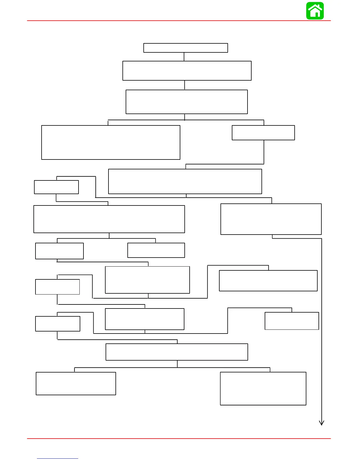
Starter Circuit Troubleshooting Flow Chart
Starter Motor Does Not Turn
SAFETY WARNING: Disconnect yellow (starter motor)
cable from starter solenoid test point 1 BEFORE making
tests 1–thru–7 to prevent unexpected engine cranking.
TEST 1
Use an ohmmeter (Rx1 scale) and connect meter leads
between NEGATIVE (–) battery post and common power-
head ground.
No Continuity Indicated – There is an open circuit in the
BLACK NEGATIVE (–) battery cable between the NEGATIVE (–)
battery post and the powerhead.
• Check cable for loose or corroded connections.
• Check cable for open.
Continuity Indicated
Proceed to TEST 2
Test 2
a. Disconnect BLACK ground wire(s) from Test Point 2.
b. Connect voltmeter between common engine ground and Test Point 2.
c. Turn ignition key to “Start” position.
No voltage reading:
proceed to TEST 3.
TEST 3
a. Reconnect BLACK ground wire.
b. Connect voltmeter between common engine ground and Test Point 3.
c. Turn ignition key to “Start” position.
12 Volt Reading*
Check BLACK ground wire for poor connection
or open circuit.
Reconnect ground wire to starter solenoid.
Proceed to TEST 7.
12 Volt Reading
Defective starter solenoid
TEST 4
a. Connect voltmeter between common
engine ground and Test Point 4.
b. Turn ignition key to “Start” position.
12 Volt Reading*
Neutral start switch is open or YELLOW/RED
wire is open between Test Points 4 and 3.
TEST 5
Connect voltmeter between common
engine ground and Test Point 5
12 Volt Reading*
Defective ignition switch.
TEST 6
Check for voltage between common engine ground and Test Point 6.
No voltage reading:
Check RED wire between battery(+)
POSITIVE terminal and Test Point 6.
12 Volt Reading*
Check fuse in RED wire between Test
Points 5 and 6.
Check for open RED wire between Test
Points 5 and 6.
*Battery Voltage
No voltage reading:
proceed to Step 4
No voltage reading:
proceed to Test 5
No voltage reading:
proceed to Test 6