WIRING DIAGRAMS
90-855347R1 JANUARY 1999 Page 2D-3
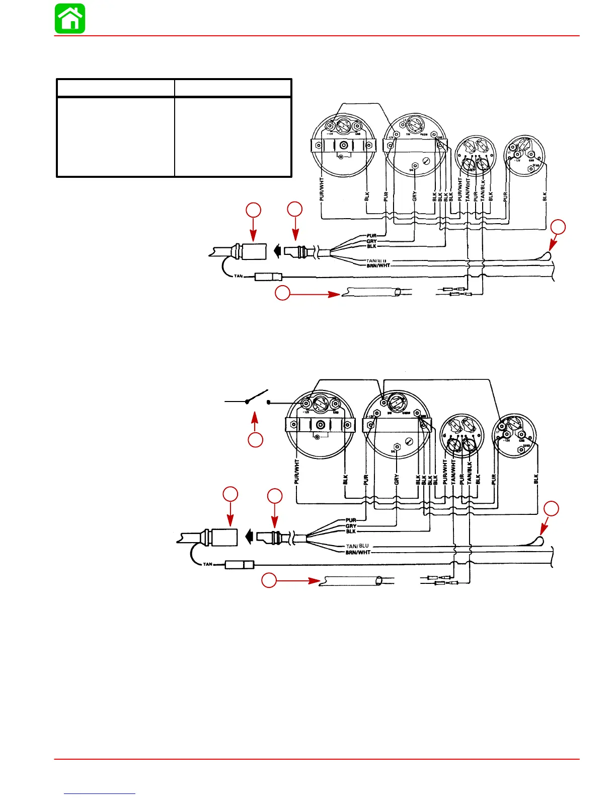
Instrument Wiring Connections
Speedometer Tachometer
Temperature/Oil
Warning Panel
Volt Meter
TAN/WHT
TAN/BLK
51820
ab
d
c
BLK = BLACK GROUND
TAN/WHT = TAN/WHITE OIL LIGHT
TAN/BLK = TAN/BLACK TEMPERATURE LIGHT
TAN = TAN TEMPERATURE GAUGE
PUR = PURPLE IGNITION 12 VOLT
GRY = GRAY TACHOMETER
BRN/WHT = BROWN/WHITE TRIM GAUGE
TAN/BLU = TAN/BLUE VISUAL WARNING KIT (OPT.)
Wire Color Where To
a
b
c
d
Figure 1 – Without Light Switch
NOTE: ANY INSTRUMENT WIRING HARNESS LEADS NOT USED MUST BE TAPED
BACK TO THE HARNESS.
TAN/WHT
TAN/BLK
Speedometer Tachometer
Temperature/Oil
Warning Panel
Volt Meter
51819
To 12V
e
a
b
d
c
a
b
c
d
e
Figure 2 – With Light Switch
a-Tachometer Receptacle - From Control Box or Ignition/Choke Switch
b-Tachometer Wiring Harness
c-Lead to Optional Visual Warning Kit (Taped Back to Harness)
d-Cable Extension (For Two Function Warning Panel)
e-Light Switch
 Loading...


