CLAMP/SWIVEL BRACKETS & DRIVE SHAFT HOUSING
Page 5A-14 90-855347R1 JANUARY 1999
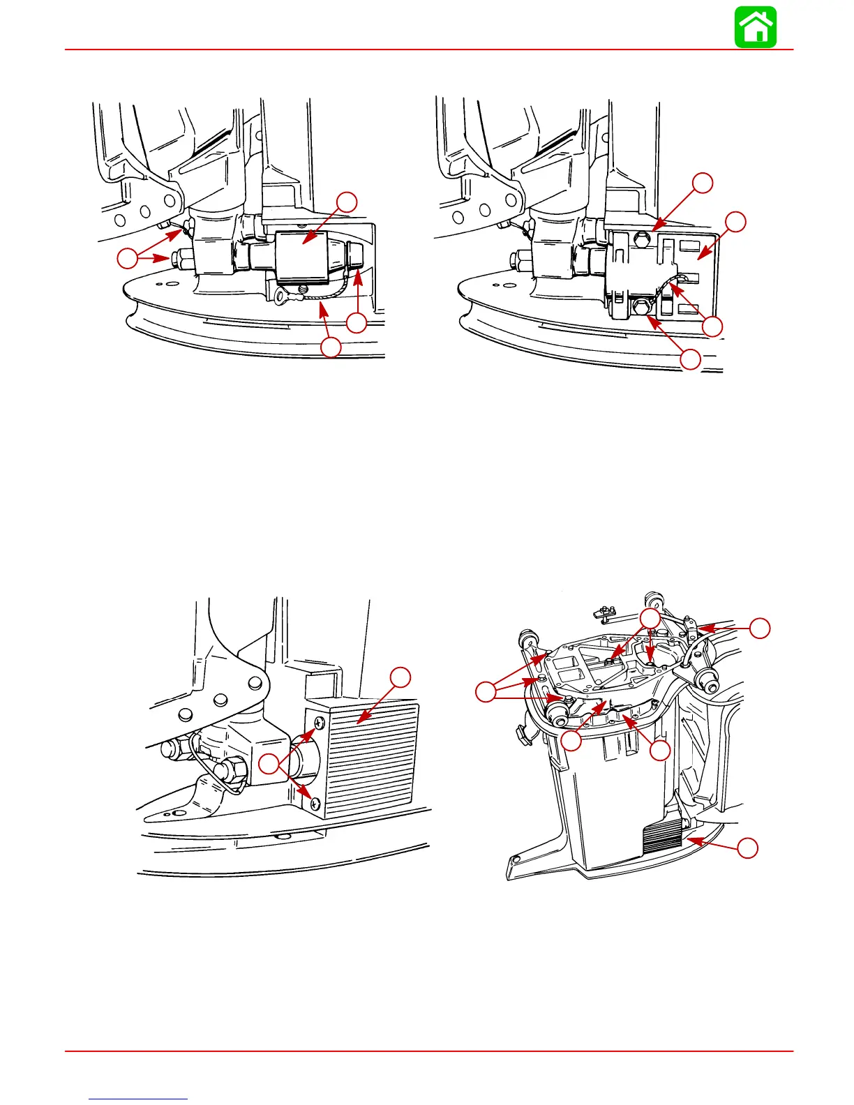
22. Install lower mount retainers and secure each retainer with 2 bolts. (Secure ground
strap with the nearest retainer bolt.) Torque bolts to 160 Ib. in. (18.0 Nm).
51855
51855
e
f
f
g
a
b
d
c
a-Lower Mount
b-Nut [Torque to 50 lb. ft. (68.0 Nm)]
c-Rubber Cap
d-Ground Strap (only one side)
e-Lower Mount Retainer
f-Bolts [Torque to 160 lb. in. (18.0 Nm)]
g-Ground Strap
23. Install lower mount covers and secure each cover with 2 screws.
24. Install exhaust extension plate on driveshaft housing with shift shaft assembly. Secure
extension plate to drive shaft housing with 5 bolts.
51858
c
d
e
f
g
h
51855
a
b
a-Cover (One Each Side)
b-Screws (Two for Each Cover)
c-Shift Shaft Linkage
d-Exhaust Extension Plate
e-Exhaust Plate to Driveshaft Housing Bolts, Torque to 25 Ib. ft. (34 Nm)
f-Drive Shaft Housing Plate
g-Lower Mount Cover (One Each Side)
h-Mounting Bracket Bolts, Torque to 40 Ib. ft. (54 Nm)
 Loading...


