EasyManuals Logo

Mercury Optimax 135 Service Manual

Mercury Optimax 135
522 pages
To Next Page IconTo Next Page
To Previous Page IconTo Previous Page
Page #325 background imageLoading...
Page #325 background image
POWER TRIM
Page 5B-20 90-855347R1 JANUARY 1999
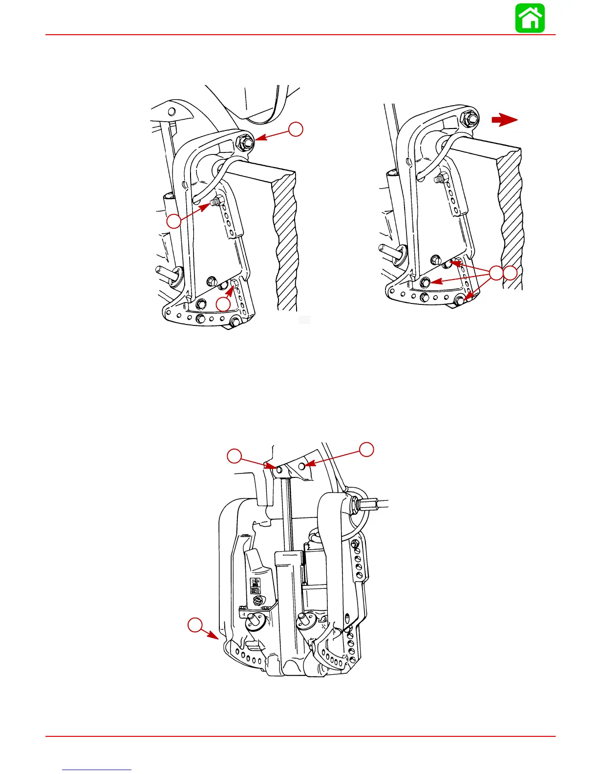
5. Remove outboard transom mounting bolts, and loosen tilt tube nut until nut is flush
with end of tilt tube thread.
6. Remove 3 screws and washers and move starboard transom bracket.
51375
51375
c
d
a
b
a
a-Transom Mount Bolts (2)
b-Tilt Tube Nut (flush with end of thread)
c-Screws (3)
d-Washers (3)
IMPORTANT: Cross pin (a) should not be reused. Replace with new cross pin.
7. Drive out cross pin, push out upper swivel pin, and remove 3 screws and washers
retaining trim system. Remove system from outboard.
a
b
c
51339
a-Cross Pin
b-Upper Swivel Pin
c-Port Transom Bracket Screws and Washers (3). Remove to Release Trim
System from Outboard.

Table of Contents

Questions and Answers:

Question and Answer IconNeed help?

Do you have a question about the Mercury Optimax 135 and is the answer not in the manual?

Mercury Optimax 135 Specifications

General IconGeneral
Engine TypeV6
Horsepower135 HP
Fuel Induction System2-stage direct fuel injection
Full Throttle RPM Range5000-5750 RPM
Alternator Output60 amp / 756 watt
Starting SystemElectric
SteeringRemote
Dry Weight431 lbs
Shaft Length20", 25"

Related product manuals